
Directly-modulated multi-polarization optical transmitters

a multi-polarization, optical transmitter technology, applied in the direction of optical waveguide light guide, optical element, instrument, etc., can solve the problems of pdm system problems, irregular rotation of the polarized light's jones vector over the entire poincaré sphere, and inability to achieve bandwidths above 100 gb/s, etc., to achieve the effect of minimizing or avoiding

Inactive Publication Date: 2014-10-23
ZTE (USA) INC
View PDF18 Cites 29 Cited by
  • Summary
  • Abstract
  • Description
  • Claims
  • Application Information

AI Technical Summary

Benefits of technology

The patent explains a way to transmit multiple signals through a medium using optical technology. These signals are synchronized so they can be sent in a way that reduces distortion and ensures they are aligned properly. This results in a more reliable and accurate transmission of information.

Problems solved by technology

Bandwidths above 100 Gb / s, however, are difficult to achieve using currently known technologies.
One issue with the use of PDM over fiber-optic transmission systems are the drifts in polarization state that may occur due to physical changes in the fiber and other factors, Over a long-distance system, these drifts may accumulate, resulting in irregular rotation of the polarized light's Jones vector over the entire Poincaré sphere.
Polarization mode dispersion, polarization-dependent loss, and cross-polarization modulation are other phenomena that may cause problems in PDM systems.

Method used


Image

  • Directly-modulated multi-polarization optical transmitters
  • Directly-modulated multi-polarization optical transmitters
  • Directly-modulated multi-polarization optical transmitters

Examples


Embodiment Construction

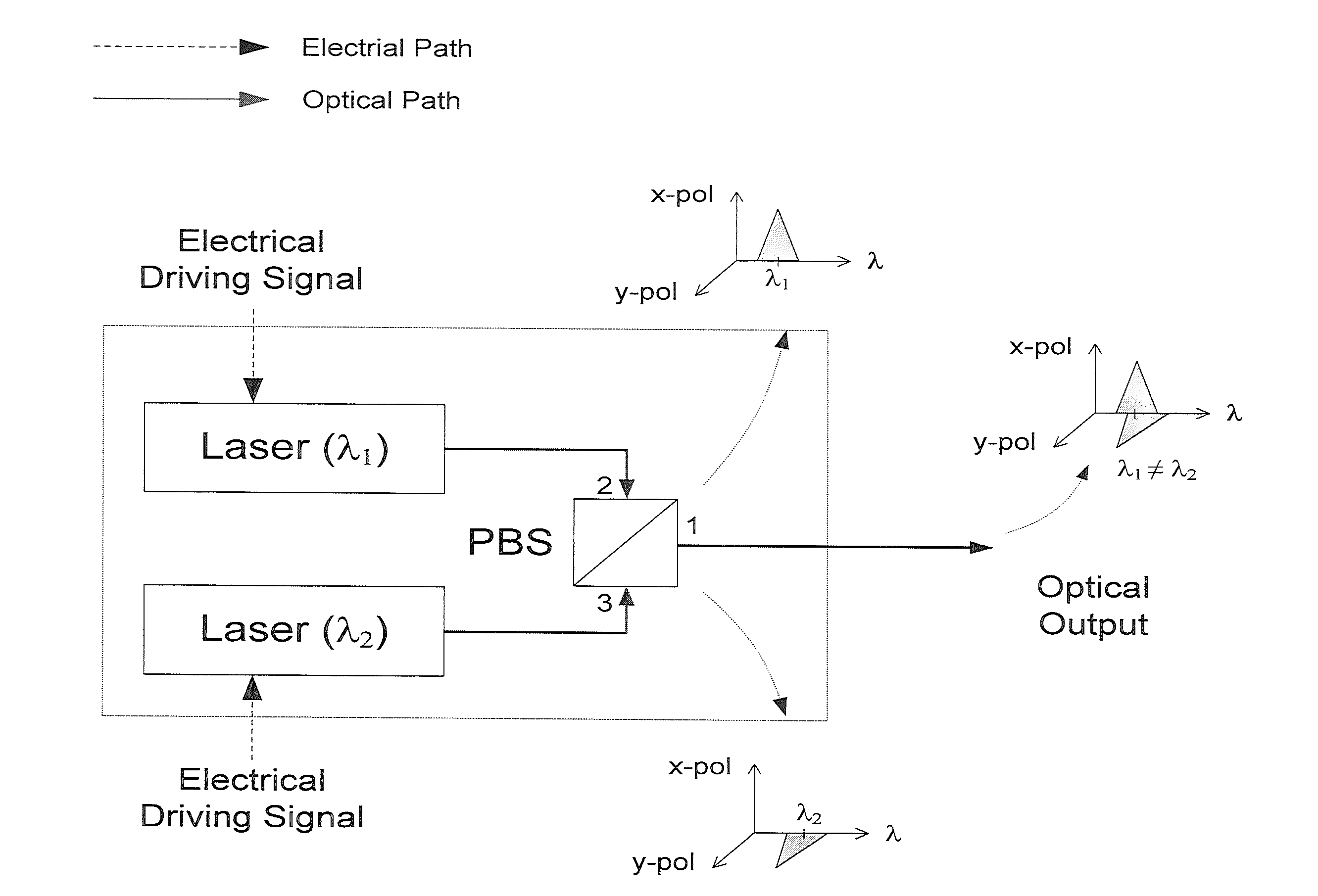
[0020]The present inventions now will be described more fully hereinafter with reference to the accompanying drawings, in which some examples of the embodiments of the inventions are shown. It is to be understood that the figures and descriptions provided herein may have been simplified to illustrate elements that are relevant for a clear understanding of the present invention, while eliminating, for the purpose of clarity, other elements found in typical optical data transmission system and methods. Those of ordinary skill in the art may recognize that other elements and / or steps may be desirable and / or necessary to implement the devices, systems, and methods described herein. However, because such elements and steps are well known in the art, and because they do not facilitate a better understanding of the present invention, a discussion of such elements and steps may not be provided herein. The present disclosure is deemed to inherently include all such elements, variations, and ...


PUM


Abstract

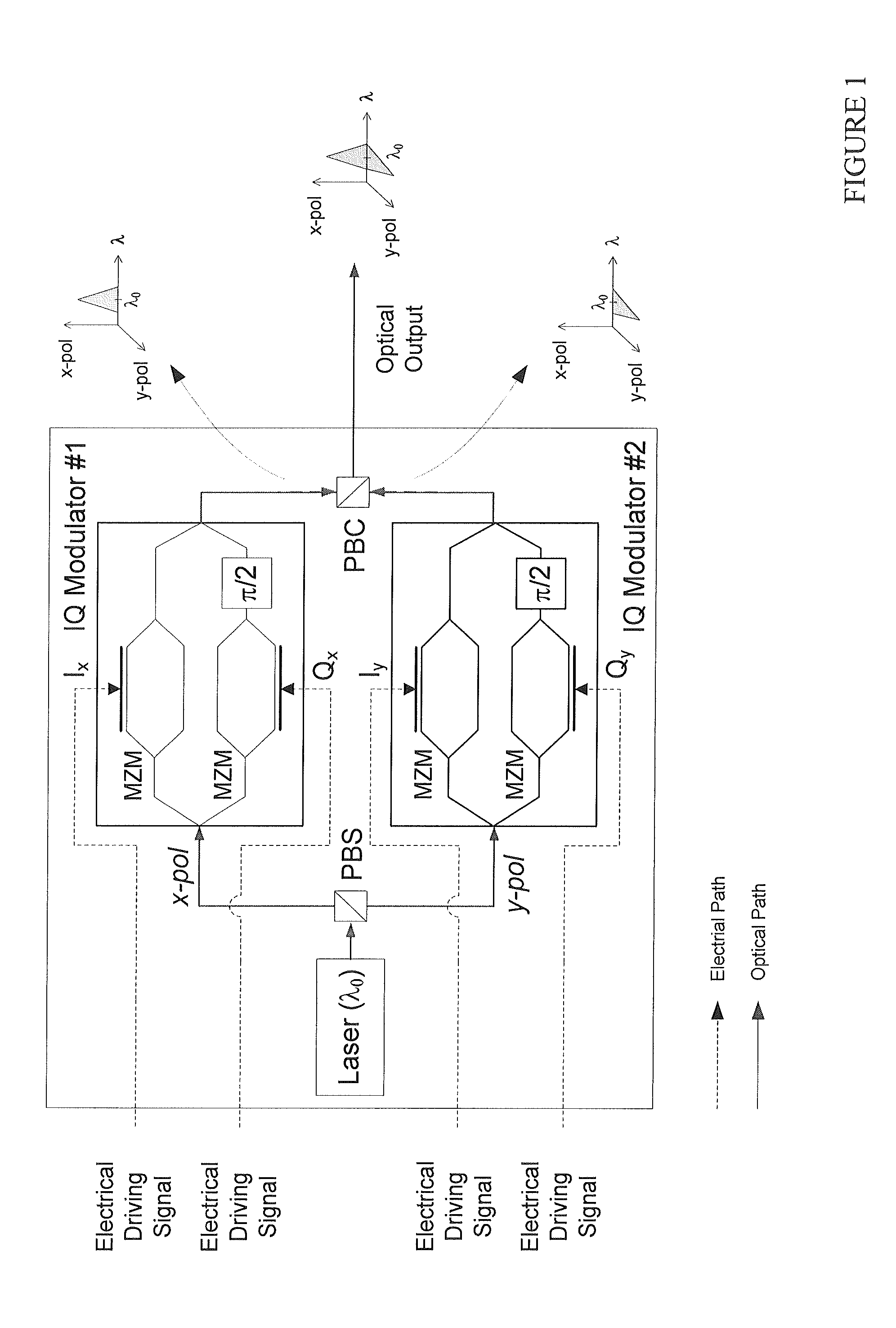
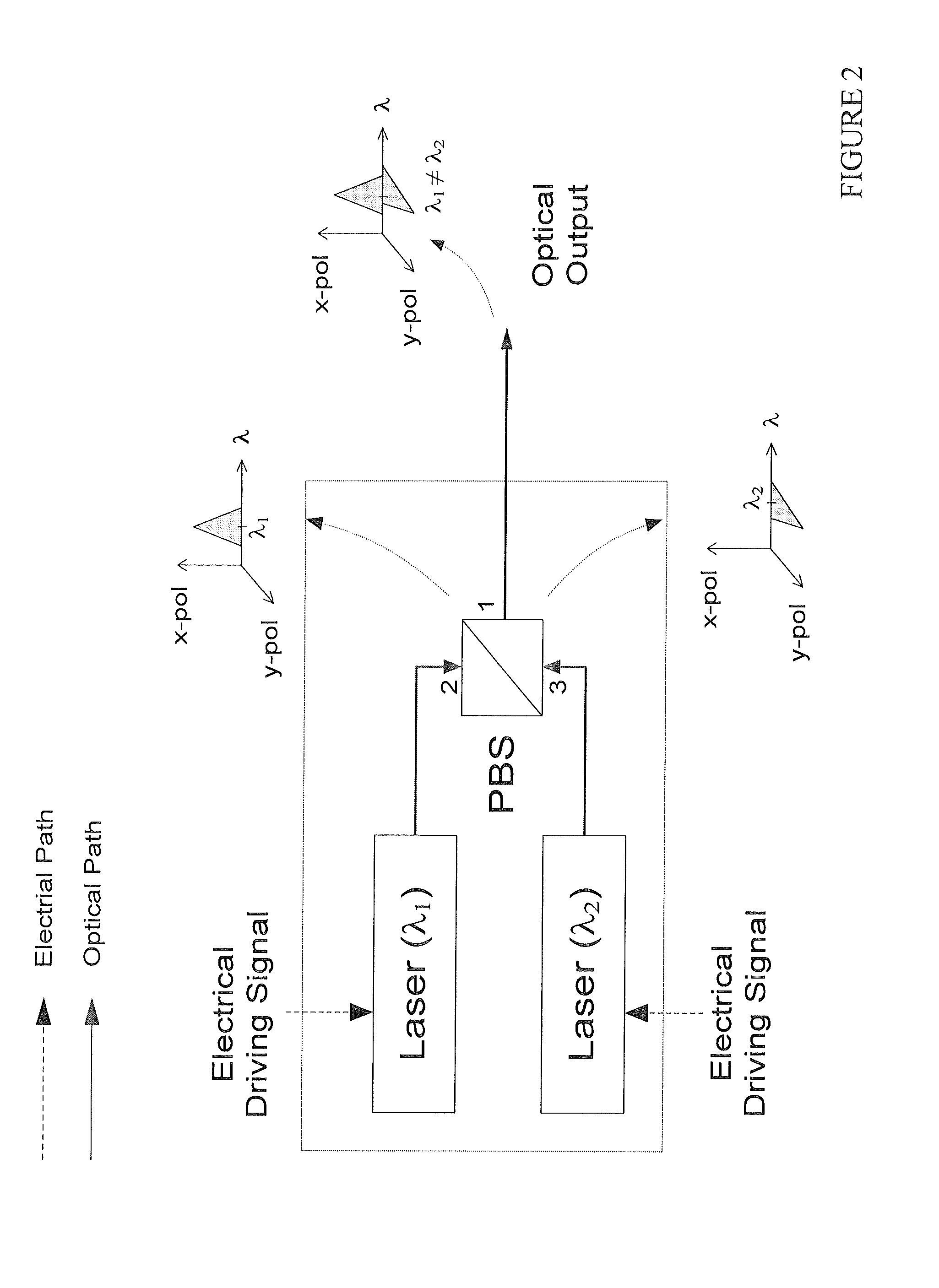
The present invention relates to optical transmitters, transceivers, and transponders used for transmission of information or data in any form through a physical medium dependent (PMD) network. The speed of such networks depends, in part, on the density of information that can be transmitted through the physical medium. Optical transmitters or transceivers can be used to transmit multiple independent signals simultaneously through the same medium using different directions or axes of polarization, where the difference in the directions or axes of polarization can be used to distinguish the multiple signals at the receiver. In this invention, we use a master laser (l0) to synchronize two slave lasers (l1 and l2) by its x-polarization and y-polarization components of carrier, respectively, so that two slave lasers can be enforced to lock on exactly the same wavelength l0 with perpendicular polarization directions.

Description

FIELD OF THE INVENTION[0001]The present invention relates generally to optical transmitters, transceivers and transponders used for transmission of information or data in any form through a physical medium dependent (PMD) network. The speed of such networks depends, in part, on the density of information that can be transmitted through the physical medium. Optical transmitters or transceivers can be used to transmit multiple independent signals simultaneously through the same medium using different directions or axes of polarization, where the difference in the directions or axes of polarization can be used to distinguish the multiple signals at the receiver. More particularly, the optical transmitter may use a master optical signal to synchronize two or more polarized optical signals so that the polarized optical signals are transmitted in phase or in synchronized form while the difference in the polarization of the optical signals is maintained.BACKGROUND[0002]There is considerabl...

Claims


Application Information

Patent Timeline
IPC IPC(8): G02B6/10
CPCG02B6/105H04B10/5053H04B10/532H04B10/5561
Inventor CHIEN, HUNG-CHANGJIA, ZHENSHENGYU, JIANJUN
Owner ZTE (USA) INC
Learn More