Image forming apparatus

a technology of image forming apparatus and forming conditions, which is applied in the direction of electrographic process apparatus, instruments, optics, etc., can solve the problems of inability to set the precise forming conditions of the toner image at the desired density, and the change of the charge amount of the toner in the developer

Inactive Publication Date: 2014-10-23
CANON KK
View PDF0 Cites 6 Cited by
  • Summary
  • Abstract
  • Description
  • Claims
  • Application Information

AI Technical Summary

Benefits of technology

[0008]Accordingly, the present invention provides an image forming apparatus capable of controlling the density of a toner image in a highly-precise manner based on a charge amount of toner in a developer.

Problems solved by technology

However, a charge amount of the toner in the developer changes when the toner in the developer is consumed and the developer is refilled with new toner during the formation of many toner images.
In other words, according to U.S. Pat. No. 5,006,897, the charge amount of the toner adhering to the photosensitive member is different from the charge amount of the residual toner detected by the probe, and thus there is a problem in that the image forming conditions for forming a toner image at a desired density cannot be set in a precise manner.

Method used


Image

  • Image forming apparatus
  • Image forming apparatus
  • Image forming apparatus

Examples


first embodiment

Apparatus Configuration

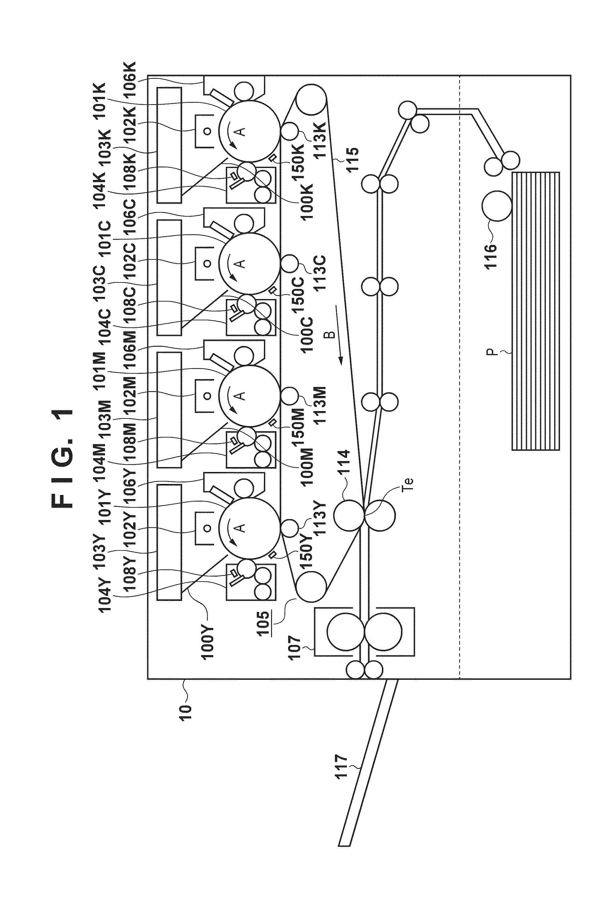
[0037]FIG. 1 is a diagram illustrating the overall configuration of an electrophotographic image forming apparatus.

[0038]Charging apparatuses 102Y, 102M, 102C, and 102K, laser scanners 103Y, 103M, 103C, and 103K, developing apparatuses 104Y, 104M, 104C, and 104K, and drum cleaners 106Y, 106M, 106C, and 106K are arranged in the periphery of photosensitive drums 101Y, 101M, 101C, and 101K, respectively. Images of respective color components are formed upon the photosensitive drums 101Y, 101M, 101C, and 101K in an image forming process, which will be described later. Here, a yellow image is formed upon the photosensitive drum 101Y, a magenta image is formed upon the photosensitive drum 101M, a cyan image is formed upon the photosensitive drum 101C, and a black image is formed upon the photosensitive drum 101K. Meanwhile, primary transfer rollers 113Y, 113M, 113C, and 113K transfer the respective color component images onto an intermediate transfer belt 115 so tha...

second embodiment

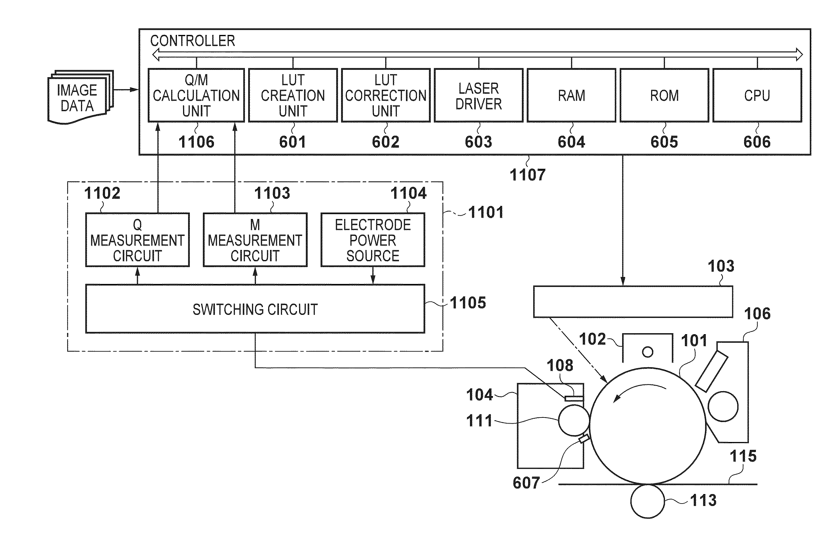
[0161]According to the first embodiment, real-time control is carried out using a configuration that corresponds to FIG. 12 and Formula (7), but because the measurement position and the exposure position are close to each other, it is possible that the control of the exposing conditions will be too late in the case where even a slight amount of delay, such as signal delay, occurs.

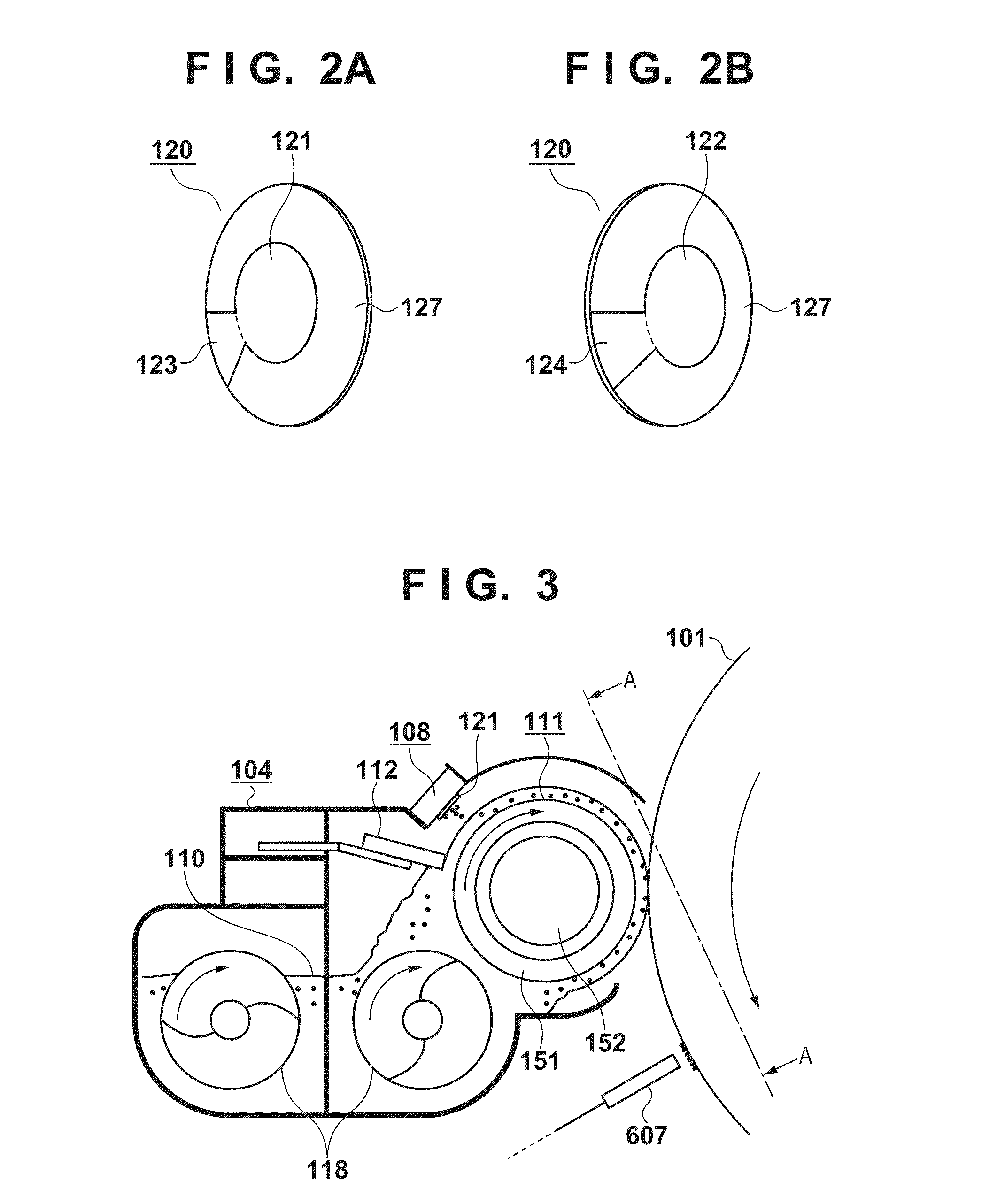
[0162]Accordingly, in the second embodiment, the configuration of the developing apparatus 104 is changed in order to lengthen the time Tqcm from the measurement position to the developing position. FIG. 24 is a schematic diagram illustrating the configuration of the developing apparatus 104 according to the second embodiment. The operations of the image forming apparatus and the operations performed in the toner charge amount measurement sequence are the same as those described in the first embodiment, and thus descriptions thereof will be omitted in the present embodiment. The developing apparatus 104 sho...

third embodiment

[0165]In the first embodiment, the charge amount measurement unit 108 is disposed in a position, facing the developing sleeve 111, in a path along which the toner on the developing sleeve 111 traverses the regulation blade 112 and reaches the developing position.

[0166]However, in the case where the conditions illustrated in FIG. 12 and indicated by Formula (7) are not met, real-time tone control cannot be carried out. For example, apparatuses that increase the rotational velocity of the developing sleeve 111 in order to increase the printing speed, apparatuses in which the diameter of the developing sleeve 111 has been reduced in order to miniaturize the apparatus, and so on may not be able to meet the condition indicated in Formula (7).

[0167]In the third embodiment, the exposing conditions are controlled in accordance with a predicted result of measuring the toner charge amount even in the case where the exposing conditions cannot be controlled in real time.

[0168]FIGS. 13A and 13B ...


PUM


Abstract

In an image forming apparatus, in the case where a time necessary for a developer bearing member to rotate from a measurement position where an attracting unit attracts the toner on the developer bearing member to a developing position at which an electrostatic latent image on the photosensitive member is developed by a toner on the developer bearing member is represented by a time Tqcm, a time necessary for the photosensitive member to rotate from an exposure position at which an exposure unit exposes the photosensitive member to the developing position is represented by a time Tetd, and a time necessary for a control unit to control an exposing condition based on a charge amount measured by a measuring unit is represented by a time Tp, the attracting unit is disposed so that Tqcm≧Tedt+Tp holds true.

Description

BACKGROUND OF THE INVENTION[0001]1. Field of the Invention[0002]The present invention relates to image forming apparatuses that control image forming conditions based on a result of detecting a charge amount of toner.[0003]2. Description of the Related Art[0004]An electrophotographic image forming apparatus forms an electrostatic latent image upon a photosensitive member based on an image of a document read by a reader, transferred from an external PC, or the like, and forms a toner image by developing the electrostatic latent image on the photosensitive member using toner in a developer. The image forming apparatus controls the density of the toner image by controlling image forming conditions such as an exposure amount of laser light emitted from an exposure apparatus for forming the electrostatic latent image on the photosensitive member, a developing bias for developing the electrostatic latent image on the photosensitive member, a charging potential for charging the photosensit...

Claims


Application Information

Patent Timeline
Patent Type & Authority Applications(United States)
IPC IPC(8): G03G15/00G03G15/043
CPCG03G13/04G03G13/08G03G15/50G03G15/0848
Inventor UCHINO, MEGUMISHIGEMURA, YOSHIHIROHORITA, SHINGONAOI, MASAAKIYAGYU, MINETO
Owner CANON KK
Why Eureka
Try Eureka