CSF shunt valve

a shunt valve and cerebrospinal fluid technology, applied in the field of medical devices, can solve problems such as the performance of shunts, and achieve the effect of facilitating self-adjustment of drainage flow

Inactive Publication Date: 2014-10-23
KING ABDULAZIZ UNIV
View PDF2 Cites 8 Cited by
  • Summary
  • Abstract
  • Description
  • Claims
  • Application Information

AI Technical Summary

Benefits of technology

[0007]The CSF shunt valve includes an elongate, hollow housing and a valve unit disposed within the housing. A plurality of exit ports are formed along the wall of the housing, and a plurality of bleeder ports are formed on the bottom of the housing. The valve unit includes at least one regulating mechanism disposed in series within the housing. Each regulating mechanism includes an obstructing member operatively attached to a spring. The spring is compressible within a predefined range of fluid pres...

Problems solved by technology

While functional, these valves can be subject to complications for the patient when the presumed pressure proves to be inaccurate, leading to improper performance of shunts, such as under- or over-drainage, neces...

Method used


Image

  • CSF shunt valve
  • CSF shunt valve
  • CSF shunt valve

Examples


Embodiment Construction

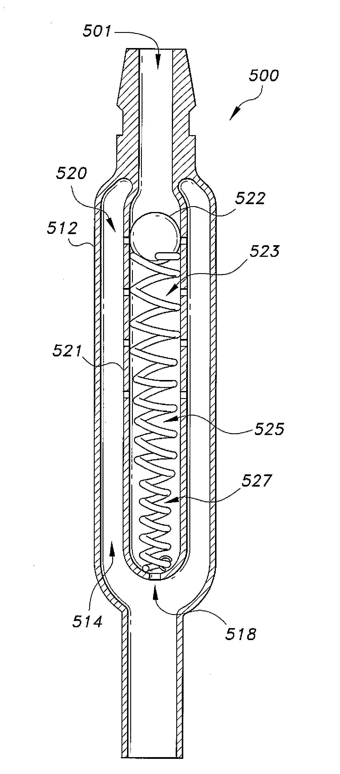
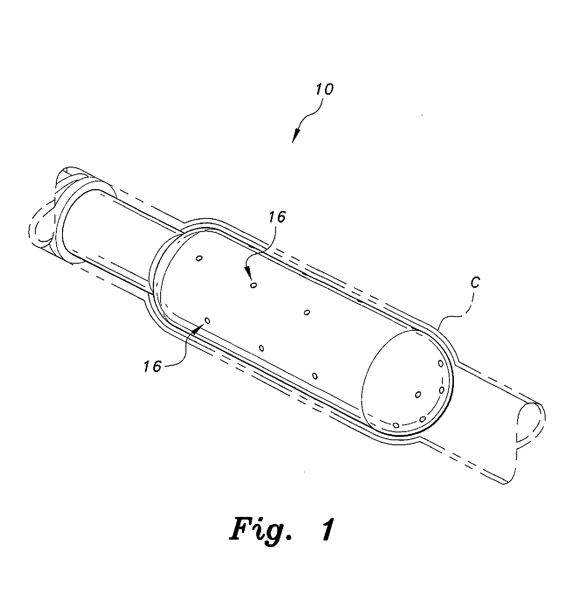
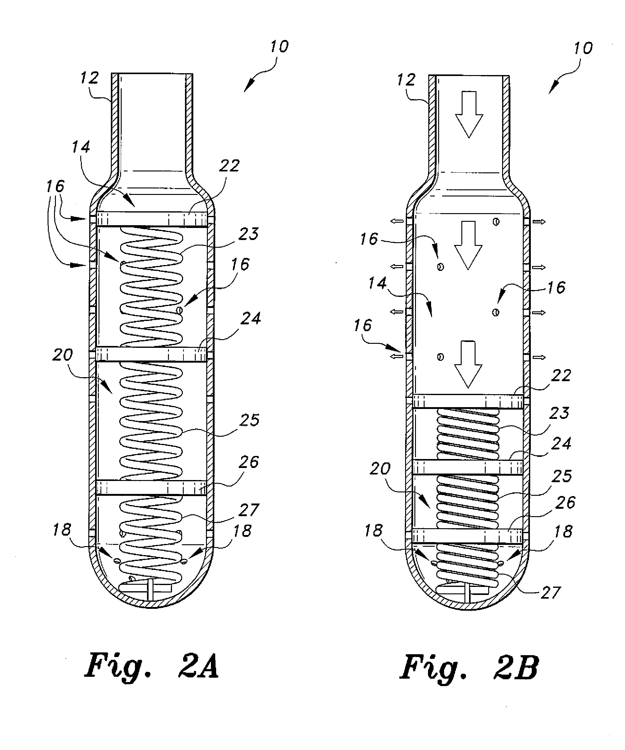
[0022]The CSF shunt valve, a first embodiment of which is generally referred to by the reference number 10, provides self-regulating flow of CSF that varies depending upon the pressure of incoming fluid flow. As best seen in FIGS. 1, 2A and 2B, the CSF shunt valve 10 is configured to be detachably mounted to a ventricular catheter C. The CSF shunt valve 10 includes an elongate, hollow valve housing 12 defining an inner collecting chamber 14. A valve unit 20 is disposed inside the collecting chamber 14. The valve unit 20 regulates flow of CSF, while the collecting chamber 14 permits accumulation of the CSF for temporary storage and drainage through the valve unit 20.

[0023]As best seen in FIG. 3A, the valve housing 12 is constructed as an elongate, substantially cylindrical tube having an open end for selective connection to the catheter C, the opposite end being substantially closed. A plurality of exit ports or holes 16 are formed radially in the cylindrical sidewall of the housing ...


PUM


Abstract

The CSF shunt valve includes an elongate, hollow housing and a valve unit disposed within the housing. A plurality of exit ports are formed along the wall of the housing, and a plurality of bleeder ports are formed on the bottom of the housing. The valve unit includes at least one regulating mechanism disposed within the housing. Each regulating mechanism includes an obstructing member operatively attached to a spring. The spring is compressible within a predefined range of fluid pressure. The obstructing member compresses the attached spring in response to fluid pressure acting thereon, opening the exit ports for fluid being drained. The spring-biased obstructing members facilitate self-adjustment for drainage flow. Although arranged in series, the range limits are not continuous with subsequent springs, which safeguards against transient spikes in fluid pressure and ensures independent compression of subsequent springs in response to the predefined limits of pressure for that spring.

Description

BACKGROUND OF THE INVENTION[0001]1. Field of the Invention[0002]The present invention relates to medical devices, and particularly to a CSF (cerebrospinal fluid) shunt valve that is self-regulating and responsive to pressure differentials from the fluid being drained or shunted.[0003]2. Description of the Related Art[0004]Obstruction of cerebrospinal fluid (CSF) or its malabsorption leads to intracranial accumulation of CSF resulting in increased intracranial pressure (ICP) or hydrocephalus. This condition requires drainage or shunting of the CSF. As with many medical conditions, the ICP varies in a case-to-case basis, taking into consideration many variables, such as the individual's age, gender, medical history and the like. Generally, the ICP can vary anywhere between 0-20 mm Hg.[0005]Typically, a sterile internal system through a catheter is used to shunt CSF into a body cavity such as the right atrium of the heart, pleural cavity or most commonly, the peritoneal cavity. An esse...

Claims


Application Information

Patent Timeline
IPC IPC(8): A61M27/00
CPCA61M27/006A61M27/002F16K15/028F16K15/063
Inventor JABER, HASSAN M. H.
Owner KING ABDULAZIZ UNIV
Why Eureka
Try Eureka