Power supply apparatus, power supply method, and storage medium

a power supply apparatus and power supply technology, applied in the direction of liquid/fluent solid measurement, instruments, inductances, etc., can solve the problems of electric power waste, inappropriate amount of electric power cannot be supplied to the power receiving apparatus, etc., and achieve the effect of reducing unnecessary electric power consumption

Active Publication Date: 2014-10-23
CANON KK
View PDF5 Cites 6 Cited by
  • Summary
  • Abstract
  • Description
  • Claims
  • Application Information

AI Technical Summary

Benefits of technology

[0006]An aspect of the present invention is generally directed to reduction of unnecessary consumption of electric power.

Problems solved by technology

However, when the power supply apparatus supplies electric power, an appropriate amount of the electric power cannot be supplied to the power receiving apparatus.
That is, the electric power is wasted.

Method used


Image

  • Power supply apparatus, power supply method, and storage medium
  • Power supply apparatus, power supply method, and storage medium
  • Power supply apparatus, power supply method, and storage medium

Examples


Embodiment Construction

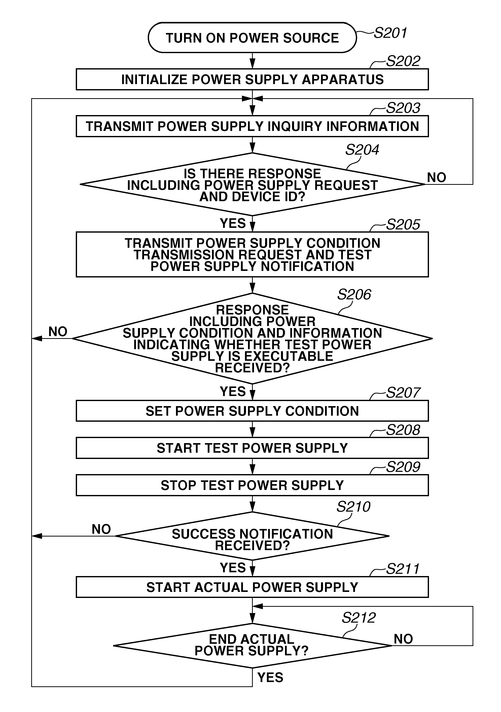
[0018]Various exemplary embodiments will be described in detail below with reference to the drawings.

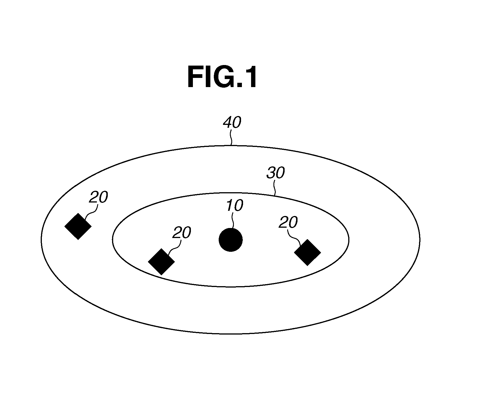
[0019]Hereinafter, a first exemplary embodiment is described. FIG. 1 is a diagram illustrating a wireless power supply system. The wireless power supply system includes a power supply apparatus 10 and a plurality of power receiving apparatuses 20. The power supply apparatus wirelessly supplies electric power to the power receiving apparatus 20. Moreover, the power supply apparatus 10 performs data communications with the power receiving apparatus 20, which are needed for the supply of power. The power receiving apparatus 20 wirelessly receives the electric power supplied from the power supply apparatus 10. Moreover, the power receiving apparatus 20 performs the data communications needed for the supply of power with the power supply apparatus 10. In a power supply area 30 illustrated in FIG. 1, the power supply apparatus 10 can supply electric power to the power receiving apparatus 2...


PUM


Abstract

A power supply apparatus includes a receiving unit configured to receive a power supply request and a power supply condition from a power receiving apparatus, and a power supply control unit configured to instruct a power supply unit to perform a test power supply to a target power receiving apparatus which is a transmission source of the power supply request, and instruct the power supply unit to perform actual power supply according to the power supply condition when the receiving unit receives a success notification of the test power supply from the target power receiving apparatus after performing the test power supply.

Description

BACKGROUND[0001]1. Field[0002]Aspects of the present invention generally relate to a power supply apparatus, a power supply method, and a storage medium.[0003]2. Description of the Related Art[0004]Conventionally, there has been provided a technique for supplying electric power in a non-contact manner (a wireless manner). There are four types of wireless power supply methods, that is, an electromagnetic induction method, a magnetic field resonance method, an electric field coupling method, and a radio wave receiving method. Among these methods, the magnetic field resonance method can transmit a sufficient amount of electric power over a long distance as its feature. With such characteristics, the magnetic field resonance method has especially received attention among these four methods. In the magnetic field resonance method, a one-to-N power supply method using the long-distance power transmission capability has been discussed (see, e.g., Japanese Patent Application Laid-Open No. 2...

Claims


Application Information

Patent Timeline
Patent Type & Authority Applications(United States)
IPC IPC(8): H04B5/00G06F1/26
CPCG06F1/26H04B5/0037H04B5/0075G06F1/266H02J50/80H02J50/402H02J50/12
Inventor AKAZAWA, MINORU
Owner CANON KK
Why Eureka
Try Eureka