Method and apparatus for crimping an electrical terminal to an electrical wire

a technology of electrical terminals and crimping devices, applied in the direction of connection contact material, manufacturing tools, coupling device connections, etc., can solve the problems of residual wire extrusion enhancement materials, oxide and/or other surface materials of aluminum as a conductor material, and the inability to crimp the electrical terminal to an electrical wir

Active Publication Date: 2014-10-30
TE CONNECTIVITY GERMANY GMBH +1
View PDF6 Cites 18 Cited by
  • Summary
  • Abstract
  • Description
  • Claims
  • Application Information

AI Technical Summary

Benefits of technology

[0004]In an embodiment, a method is provided for crimping an electrical terminal to an electrical wire having electrical conductors. The method includes positioning the electrical wire and the electrical terminal between opposing crimp tooling members of a crimp tool. The method also includes pressing a crimp barrel of the electrical terminal against the electrical conductors of the electrical wire using the crimp tooling members such that the electrical conductors are mechanically and electrically connected to the crimp barrel. The crimp barrel is pressed against the electrical conductors such that at least some contact portions of metallic surfaces of at least some of the electrical conductors melt and form hot weld bonds with one or more contact portions of the metallic surface of one or more adjacent electrical conductors.
[0005]In an embodiment, a crimp tool is provided for crimping an electrical terminal to an electrical wire having electrical conductors. The crimp tool includes a base and a pair of opposing crimp tooling members held by the base. The crimp tooling members are configured to move toward and away from each other along a crimping axis. The crimp tooling members include pressing surfaces that are configured to engage in physical contact with a crimp barrel of the electrical terminal. A crimp zone is defined between the pressing surfaces of the crimp tooling members. The crimp zone is configured to receive an assembly of the electrical wire and the electrical terminal. The crimp tool includes an actuator that is operatively connected to at least one of the crimp tooling members for moving the at least one crimp tooling member relative to the base. The actuator is configured to move the crimp tooling members toward each other along the crimping axis such that the crimp tooling members press the crimp barrel of the electrical terminal against the electrical conductors of the electrical wire and such that at least some contact portions of metallic surfaces of at least some of the electrical conductors melt and form hot weld bonds with one or more contact portions of the metallic surface of one or more adjacent electrical conductors.

Problems solved by technology

But, using aluminum as a conductor material is not without disadvantages.
For example, one disadvantage of using aluminum as a conductor material is an oxide and / or other surface material (e.g., residual wire extrusion enhancement materials) layer that may build on the exterior surface of the conductor when the conductor is exposed to atmosphere and / or during processing of the conductor.
For example, such aluminum oxide layers can have relatively poor electrical connection properties as compared to metallic aluminum.
Such oxide and / or other surface material layers may be formed on other conductor materials, but can be especially difficult to deal with for aluminum.
But, it may be difficult to displace enough of the oxide layer to achieve a sufficient electrical and mechanical bond, and thereby establish a reliable electrical connection, because of the tenacity and relatively high speed at which the oxide layer forms on the conductors.
But, it may be difficult to displace enough of the oxide layer to achieve a sufficient electrical and mechanical bond during the crimping operation and / or before new oxide forms on the exposed aluminum material.

Method used


Image

  • Method and apparatus for crimping an electrical terminal to an electrical wire
  • Method and apparatus for crimping an electrical terminal to an electrical wire
  • Method and apparatus for crimping an electrical terminal to an electrical wire

Examples


Embodiment Construction

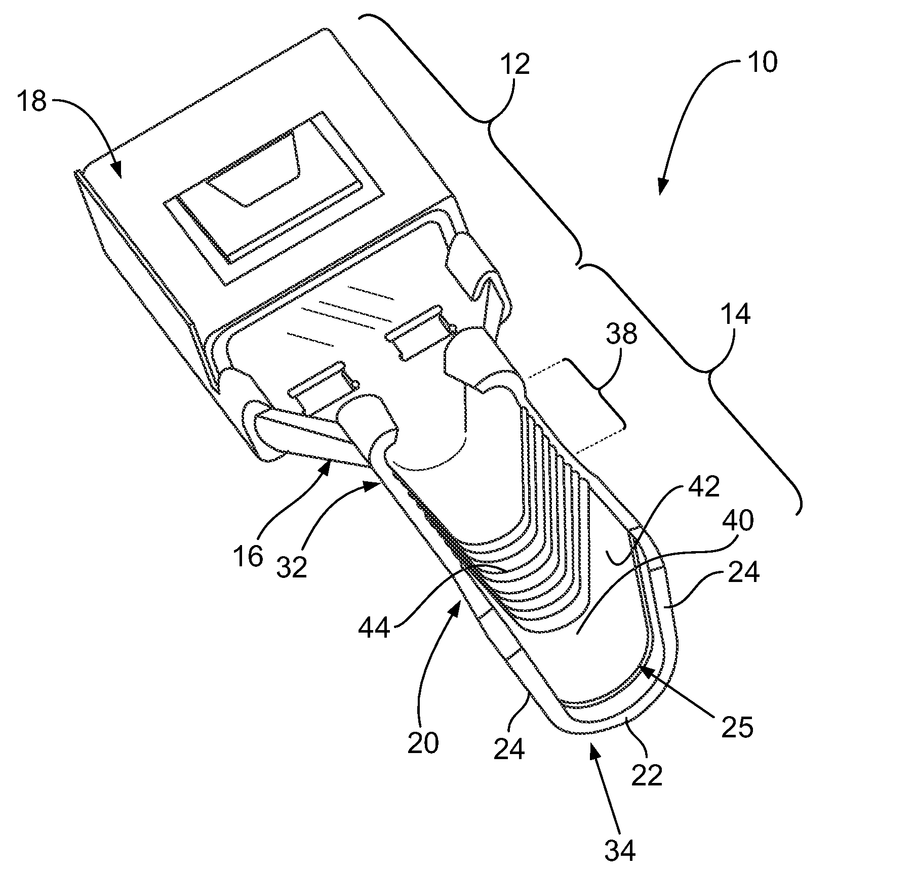
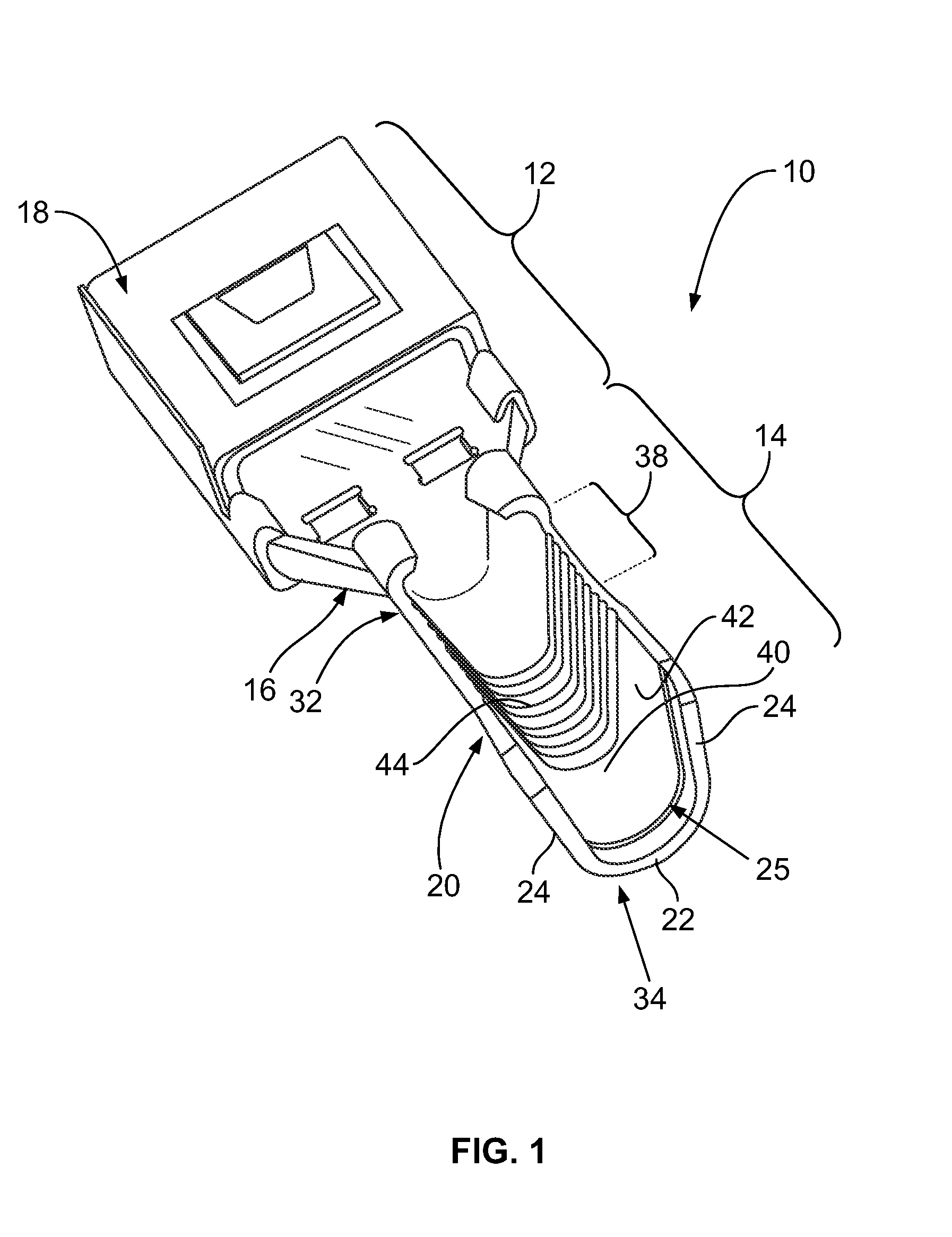
[0014]FIG. 1 is a perspective view of an embodiment of an electrical terminal 10. The terminal 10 includes an electrical contact segment 12 and a crimp segment 14 that extends from an end 16 of the electrical contact segment 12. The electrical contact segment 12 includes an electrical contact 18. In the illustrated embodiment, the electrical contact 18 is a receptacle that is configured to receive a mating contact (not shown) therein. But, the electrical contact 18 shown herein is meant as exemplary only. The electrical terminal 10 is not limited to the electrical contact 18 shown herein, but rather the electrical terminal 10 may include any type of electrical contact 18, such as, but not limited to, a crimp barrel, a spring contact, a beam contact, a tab, a structure having an opening for receiving a threaded or other type of mechanical fastener, and / or the like.

[0015]The crimp segment 14 includes a crimp barrel 20. The crimp barrel 20 includes a base 22 and opposing side walls 24 ...


PUM

PropertyMeasurementUnit
speedaaaaaaaaaa
speedaaaaaaaaaa
electricalaaaaaaaaaa

Abstract

A method is provided for crimping an electrical terminal to an electrical wire having electrical conductors. The method includes positioning the electrical wire and the electrical terminal between opposing crimp tooling members of a crimp tool. The method also includes pressing a crimp barrel of the electrical terminal against the electrical conductors of the electrical wire using the crimp tooling members such that the electrical conductors are mechanically and electrically connected to the crimp barrel. The crimp barrel is pressed against the electrical conductors such that at least some contact portions of metallic surfaces of at least some of the electrical conductors melt and form hot weld bonds with one or more contact portions of the metallic surface of one or more adjacent electrical conductors.

Description

BACKGROUND OF THE INVENTION[0001]The subject matter described and / or illustrated herein relates generally to electrical terminals that terminate wires.[0002]Electrical terminals are often used to terminate the ends of wires. Such electrical terminals typically include an electrical contact and a crimp barrel. The crimp barrel includes an opening that receives an end of the wire therein. The crimp barrel is crimped around the end of the wire to establish an electrical connection between the one or more conductors of the wire and the terminal as well as to mechanically hold the electrical terminal on the wire end. When crimped over the wire end, the crimp barrel establishes an electro-mechanical connection between the conductor(s) of the wire and the electrical contact.[0003]Conductors of wires are often fabricated from copper, copper alloys, copper clad steel, etc. However, as the cost of copper has risen, aluminum has represents a lower cost alternative conductor material. But, usin...

Claims


Application Information

Patent Timeline
Patent Type & Authority Applications(United States)
IPC IPC(8): H01R13/422
CPCH01R13/422H01R4/08H01R4/187H01R4/62H01R43/048H01R43/0207Y10T29/53213Y10T29/49185
Inventor SCHMIDT, HELGEMYERS, MARJORIE KAYKARRASCH, CHRISTOPHER J.
Owner TE CONNECTIVITY GERMANY GMBH
Why Eureka
Try Eureka