Foundation for a wind turbine

Active Publication Date: 2014-10-30
WOBBEN PROPERTIES GMBH
View PDF19 Cites 24 Cited by
  • Summary
  • Abstract
  • Description
  • Claims
  • Application Information

AI Technical Summary

Benefits of technology

[0023]A pylon base arrangement which uses connecting bolts can thus provide for the application of force from the pylon, in particular from the lower pylon segment, into the foundation, in two ways. The transmission of force, that is to say in particular tensile forces, can thus be implemented on the one hand from the lower pylon segment directly by way of the inner fixing bolts into the foundation. In addition, such forces can be in part passed to the pylon base section by way

Problems solved by technology

Another disadvantage in that respect is that this pylon base section has to be held by the holding device upon pouring and setting of the concrete.
That kind of pylon base section can also involve problems in terms of erecting and thus anchoring very large wind power installation pylons.
A problem in that respect is that, when pouring the concrete, the connecting bars have to be oriented with a template or jig in the region of the concrete surface or foundation surface to be produced, so that the connecting bars are correctly arranged after the concrete has set and can extend without any problem through the large number of bores in the levelling ring to be arranged, and the flange of the lo

Method used


Image

  • Foundation for a wind turbine
  • Foundation for a wind turbine
  • Foundation for a wind turbine

Examples


Embodiment Construction

[0042]Hereinafter the same references are possibly used for similar but non-identical features to improve understanding of the functionality of the respective components.

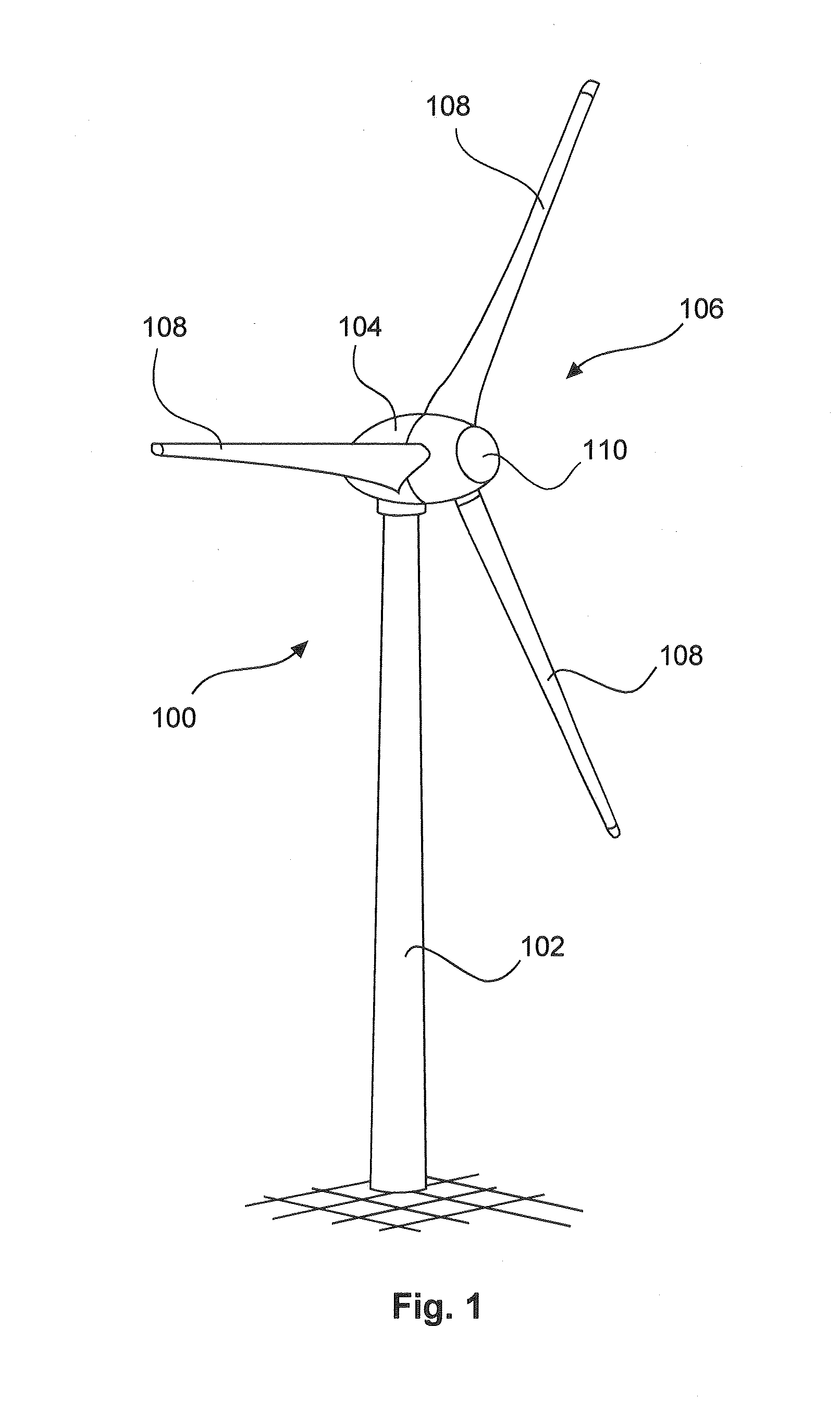
[0043]FIG. 1 shows a wind power installation 100 comprising a pylon 102 and a pod 104. Arranged on the pod 104 is a rotor 106 having three rotor blades 108 and a spinner 110. In operation the rotor 106 is caused to rotate by the wind and thereby drives a generator in the pod 104.

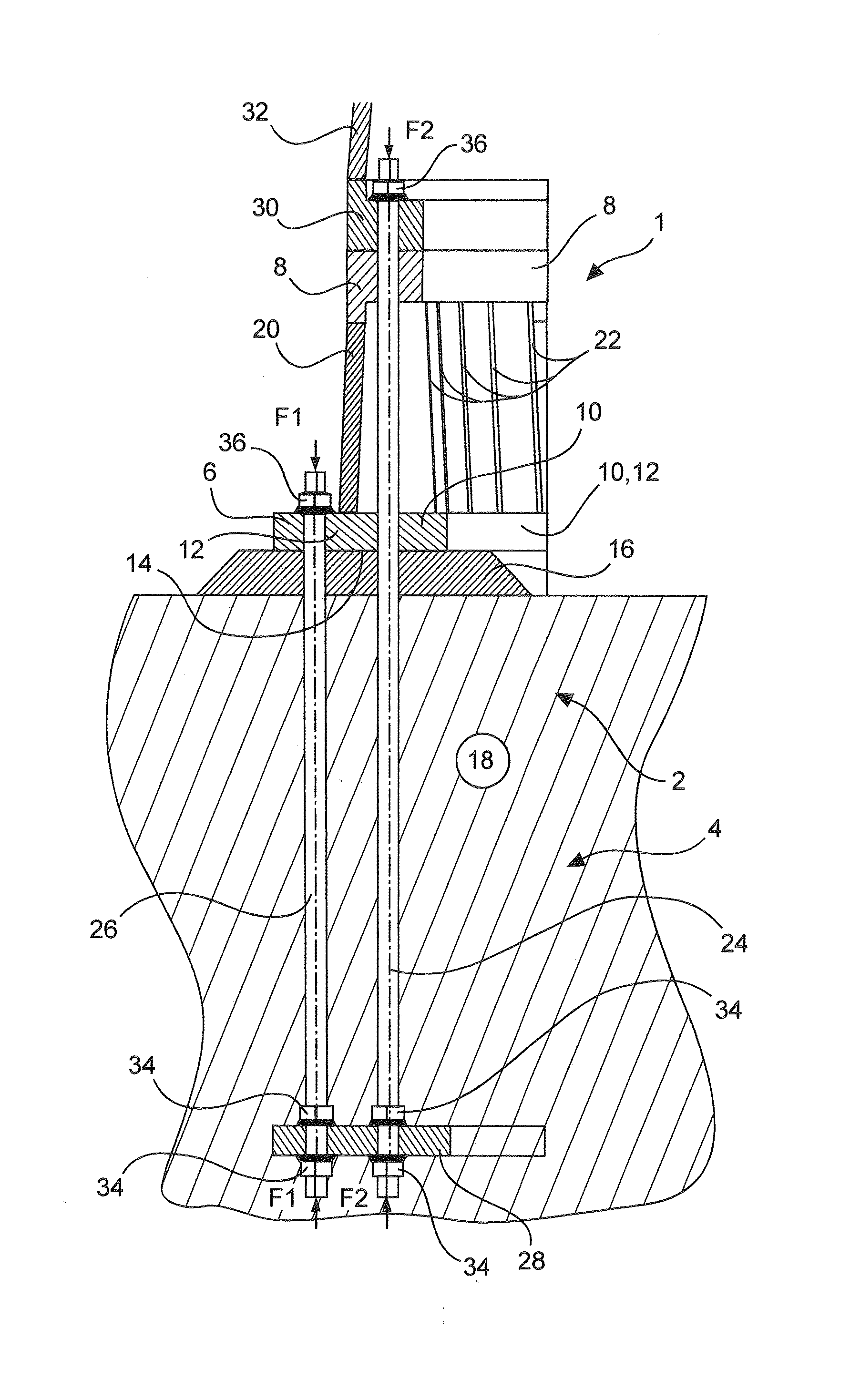
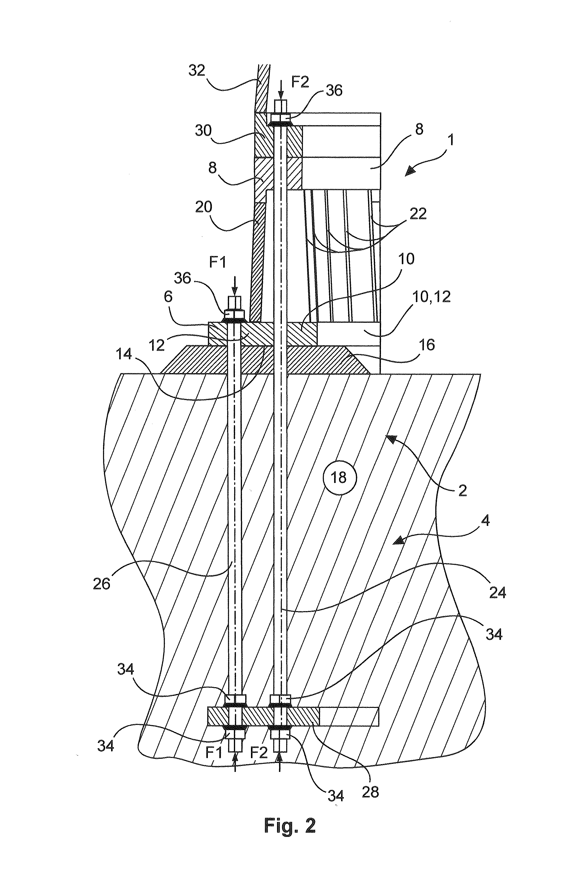
[0044]The pylon base arrangement 2 in FIG. 2 includes a pylon base section 1 and a pylon basket 4 which can also be referred to as a bolt basket.

[0045]The pylon base section 1 includes an outer lower annular flange 6, an inner upper annular flange 8 and a lower inner support flange 10 which is also in the form of an annular flange. The outer lower annular flange 6 and the lower inner support flange 10 basically together form a lower annular base portion 12. That lower annular base portion 12 can be made from one piece, in particular of steel...


PUM


Abstract

The invention concerns a pylon base section for arrangement and fixing on a foundation and for the erection of a pylon of a wind power installation thereon including an outer lower annular flange for placement on the foundation and for fixing to the foundation, an inner upper annular flange for placement and fixing of a pylon segment with a corresponding lower pylon flange thereon, an inner lower support flange for placement on the foundation, and inner support elements, in particular support struts, for supporting the upper annular flange relative to the lower support flange.

Description

BACKGROUND[0001]1. Technical Field[0002]The present invention concerns a pylon base section for the erection of a wind power installation. The present invention further concerns a pylon base arrangement having a pylon base section. The present invention also concerns a pylon of a wind power installation and a method of erecting a pylon of a wind power installation.[0003]2. Description of the Related Art[0004]Wind power installations are generally known and are frequently erected on a pylon, as is also the case with the wind power installation shown in FIG. 1. Such a pylon of a wind power installation, namely a wind power installation pylon, is erected for that purpose on a suitable foundation. In that case care is also to be taken to provide for perpendicular orientation or levelling of the pylon.[0005]To prepare for erecting a wind power installation pylon it is known for a pylon base section to be partly concreted into the foundation in order to erect the further pylon thereon. Su...

Claims


Application Information

Patent Timeline
IPC IPC(8): F03D11/04E04H12/34
CPCE04H12/34F03D11/045E02D27/42F03D13/22Y02E10/728Y02E10/72
Inventor COORDES, THOMAS
Owner WOBBEN PROPERTIES GMBH
Why Eureka
Try Eureka