

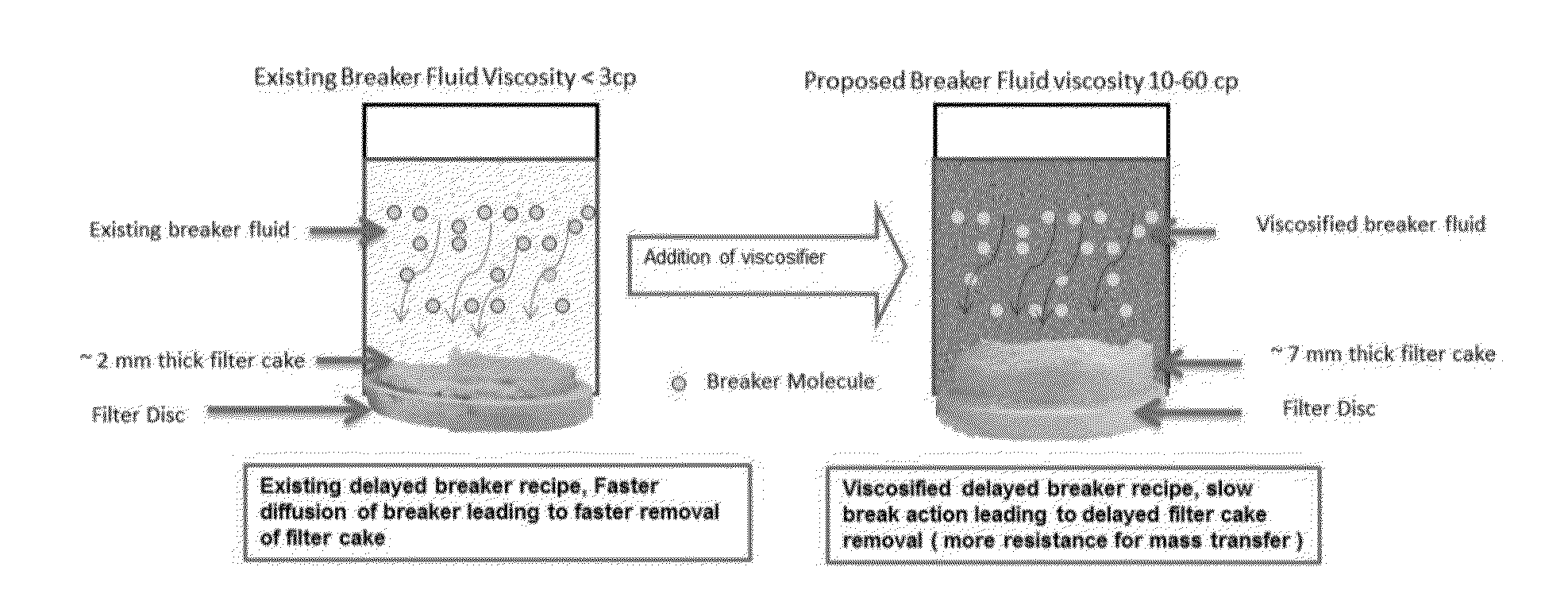
Viscosified breaker fluid compositions for extended delay in filtercake removal at high temperature
a technology of breaker fluid and high temperature, which is applied in the direction of fluid removal, chemistry apparatus and processes, and wellbore/well accessories, etc., can solve the problems of reducing production rate, difficult to optimize breaker recipe to achieve desired delay to suit job requirements, and difficult to retard breaker action. , to achieve the effect of prolonging or delaying the break tim
- Summary
- Abstract
- Description
- Claims
- Application Information
AI Technical Summary
Benefits of technology
Problems solved by technology
Method used
Image

Examples
example 1
[0101]In a recent situation, a customer from Asia Pacific region was looking for a break time of 5-6 hours using an existing breaker system. Temperature of the targeted zone was 250° F. In laboratory testing, using a minimum concentration of alkyl lactate (12%), the maximum delay that was achieved at 250° F. was approximately 33 mins. This was possibly due to faster release of organic acid at such a high temperature. In order to achieve the delay of 5-6 hrs, lab tests were conducted by addition of a locally available viscosifier to the breaker fluid. Different concentrations of the viscosifier were added to evaluate the effect of viscosity on the break times.
[0102]Results of the Laboratory testing are as follows,
Intial ViscosityBreakerBreakCompleteFinal ViscosityTestof breaker fluidconcentrationInitialFinalTime inClean upof breakerNo.in cPViscosifier% V / VpHpHhrsTime in hrsfluid in cP1No126.53.2~0.530210Liqui Vis EP106.544.182.5302342Liqui Vis EP106.473.765.4304459Liqui Vis EP106.44....
example 2
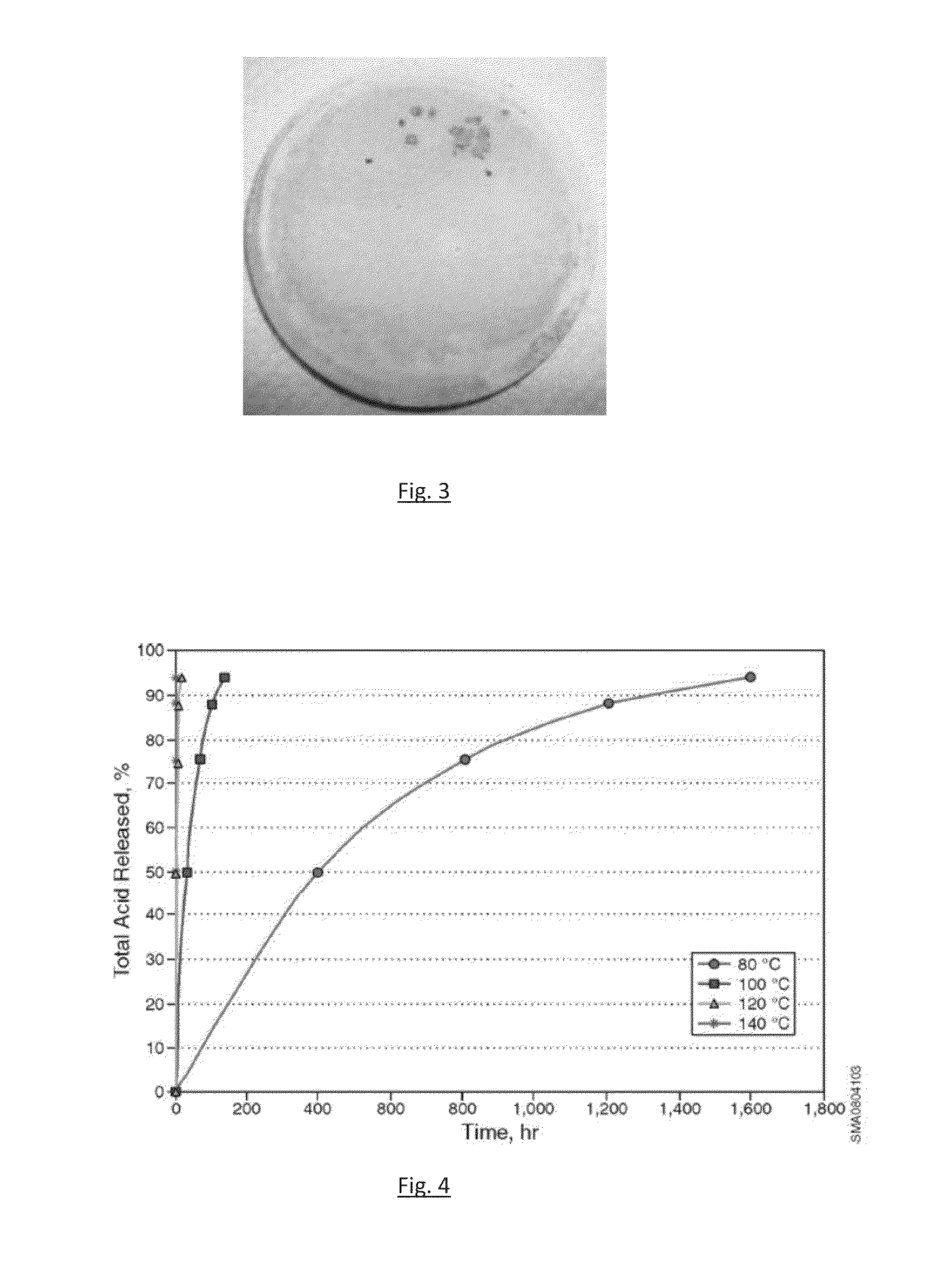
[0104]An alkyl formate ester was used for delayed filter cake clean-up, for temperatures up to 194° F., and an alkyl lactate for temperatures up to 284° F. At higher temperatures (>220F), it became difficult to optimize a breaker recipe to achieve delay of a few hours break time. Work confirmed that it was challenging to get delayed break time by using alkyl lactate at 250° F., even with the minimum concentrations used. The graph at FIG. 4 illustrates the rate of acid release of alkyl lactate with time and temperature. The rate of acid release shown therein further confirms this challenge.
PUM
| Property | Measurement | Unit |
|---|---|---|
| temperature | aaaaa | aaaaa |
| temperature | aaaaa | aaaaa |
| pressure | aaaaa | aaaaa |
Abstract
Description
Claims
Application Information