Power control unit

a power converter and control unit technology, applied in the direction of electric devices, propulsion by batteries/cells, transportation and packaging, etc., can solve the problems of large cabling size, noise from the electric power converter module is blocked by the partition wall, and the charging device produces noise, so as to reduce the adverse effect of noise caused by the electric power converter module on the controller and not be adversely affected by nois

Active Publication Date: 2014-10-30
HONDA MOTOR CO LTD
View PDF3 Cites 9 Cited by
  • Summary
  • Abstract
  • Description
  • Claims
  • Application Information

AI Technical Summary

Benefits of technology

[0011]With the power control unit according to the present invention, noise from the electric power converter module is blocked by the partition wall. Therefore, the adverse effect of noise caused by the electric power converter module on the controller can be reduced. Since the charging device does not operate while the controller is in operation, the controller is not adversely affected by noise from the charging device. On the other hand, while the charging device is in use, the charging device produces noise. However, as the controller is not in operation, there is no need to worry about noise from the charging device.

Problems solved by technology

According to the technology disclosed in Japanese Laid-Open Patent Publication No. 2010-035347, however, since the casing of the electric power converter is of a three-layer structure for housing the inverter circuit, a controller, etc. therein, the casing is large in size.
Consequently, noise from the electric power converter module is blocked by the partition wall.
On the other hand, while the charging device is in use, the charging device produces noise.

Method used


Image

  • Power control unit
  • Power control unit
  • Power control unit

Examples


Embodiment Construction

[0022]An electric vehicle which has a power control unit according to a preferred embodiment of the present invention will be described in detail below with reference to the accompanying drawings.

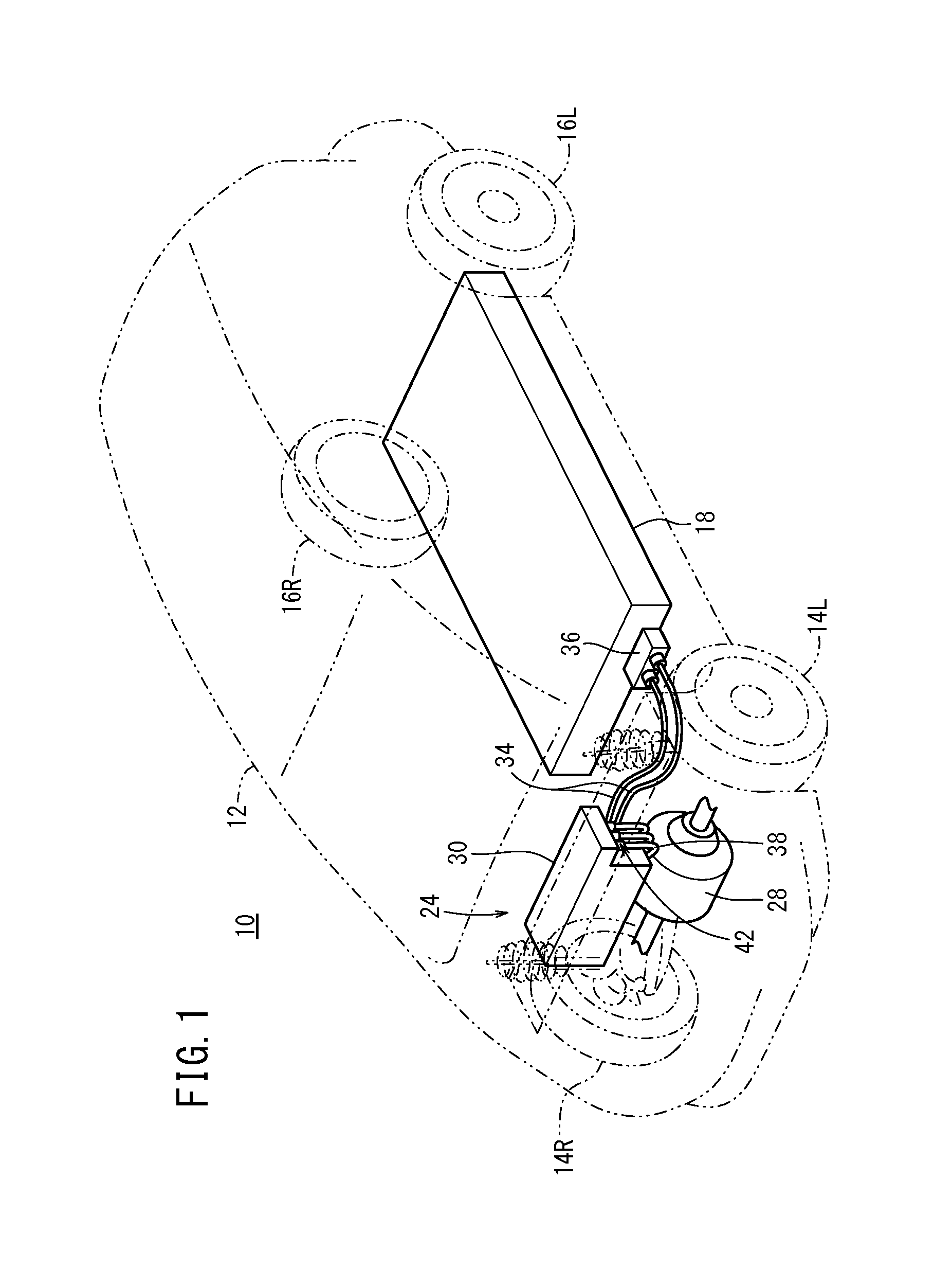
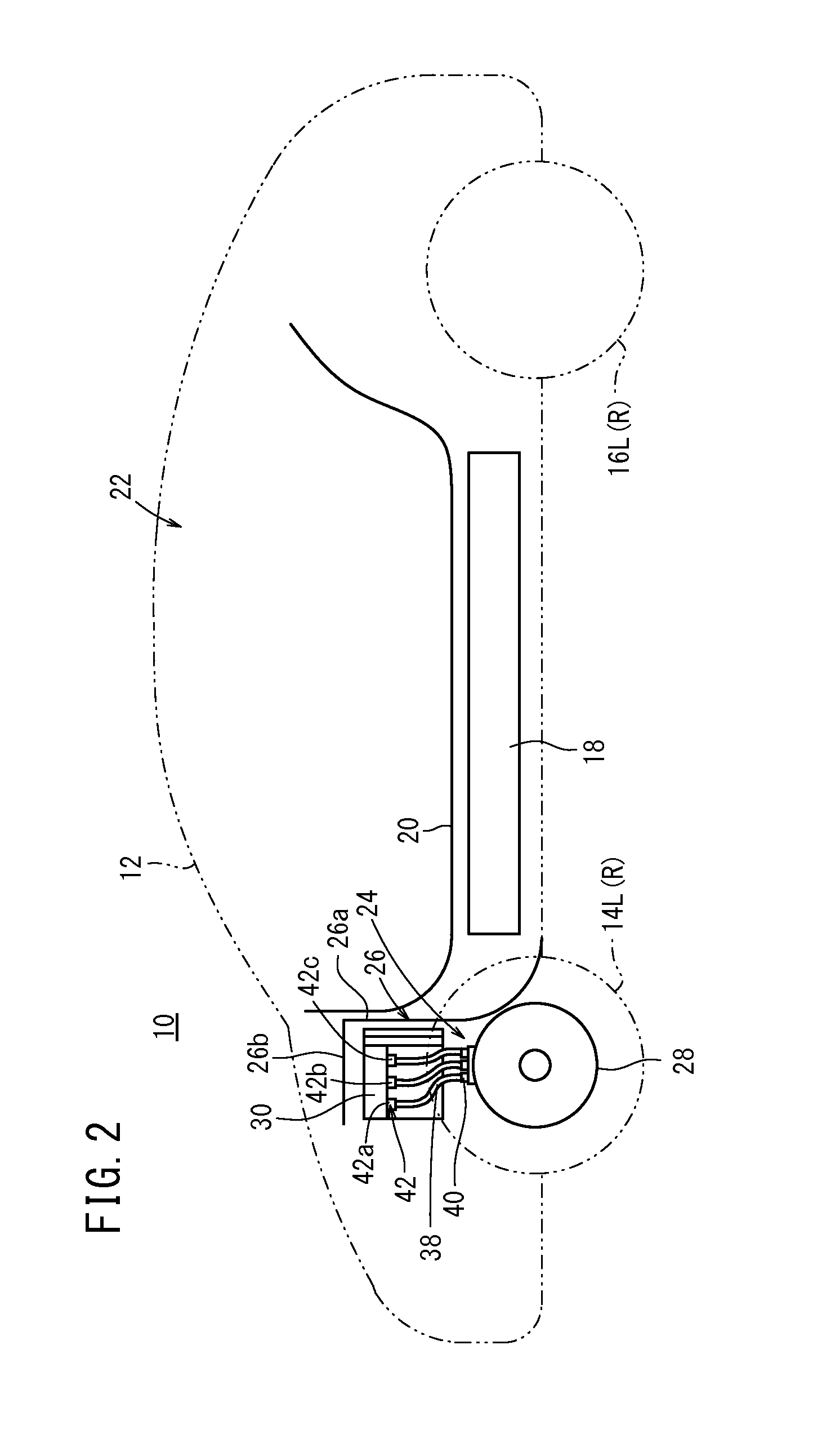
[0023]FIG. 1 is a perspective view schematically showing a general arrangement of an electric vehicle (vehicle) 10, and FIG. 2 is a side elevational view schematically showing the general arrangement of the electric vehicle 10. In the present embodiment, the vertical directions of a vehicle body 12 of the electric vehicle 10 are referred to as up and down directions, and directions perpendicular to the vertical directions are referred to as horizontal directions. The direction in which the electric vehicle 10 travels forwardly is referred to as a forward direction, and the direction in which the electric vehicle 10 reverses is referred to as a rearward direction. Further, the direction on the left side as viewed along the forward direction is referred to as a leftward direction, and the dir...


PUM


Abstract

This power control unit, which stores a power conversion module and a rapid charging device used when charging a battery, is provided with a power conversion chamber, which houses the power conversion module, and a charging device chamber, which houses the charging device, the power conversion chamber and the charging device chamber have a bottom surface in common with each other, the power conversion module and the charging device are affixed to the bottom surface in the respectively corresponding chambers, and an ECU that controls the power conversion module is disposed at a position that is above the charging device and enclosed by a peripheral wall that includes the partition wall that partitions the charging device chamber and the power conversion chamber.

Description

TECHNICAL FIELD[0001]The present invention relates to a power control unit including an electric power converter module having a switching element and configured to convert direct-current power into alternating current and a controller configured to control the electric power converter module, wherein the controller is protected from noise generated by the switching element of the electric power converter module.BACKGROUND ART[0002]Heretofore, there has been a situation in which noise is produced by the switching element of an inverter circuit and the noise adversely affects a controller for controlling the inverter circuit. Thus, there has been devised a controller layout in view of the adverse effect of the noise produced by the switching element.[0003]Japanese Laid-Open Patent Publication No. 2010-035347 discloses that, in view of noise produced by a power module that includes an inverter circuit (having switching elements), an electric power converter is of a three-layer structu...

Claims


Application Information

Patent Timeline
Patent Type & Authority Applications(United States)
IPC IPC(8): B60L11/18
CPCB60L11/1803B60L3/003B60L2210/10B60L2210/30B60L2240/34B60L2240/36B60L2240/525B60L2240/545B60L50/51B60L50/52B60L50/66B60L53/11B60L53/16Y02T10/70Y02T10/7072Y02T10/72Y02T90/14Y02T90/12
Inventor SUZUKI, YUUICHISUZUKI, TOMOYUKI
Owner HONDA MOTOR CO LTD
Why Eureka
Try Eureka