Method and apparatus for adjusting the contrast of an image

a technology of contrast adjustment and image, applied in image data processing, color television, television systems, etc., can solve the problems of noise in smooth areas of images, excessive or poor lighting conditions, ringing or overshooting effect around edges or other regions of high contrast, etc., to achieve reduced noise, increase contrast, and computational efficiency.

Active Publication Date: 2008-01-17
VESTEL ELEKTRONIK SANAYI & TICARET ANONIM SIRKETI
View PDF19 Cites 9 Cited by
  • Summary
  • Abstract
  • Description
  • Claims
  • Application Information

AI Technical Summary

Benefits of technology

[0018] In a preferred embodiment, the high frequency component is amplified by a gain that varies in dependence on the magnitude of the high frequency component obtained in the filtering step, and preferably varies only in dependence on the magnitude of the high frequency component obtained in the filtering step. In this way, the enhancement that is applied to the original image can be made to vary according to the local characteristics in the image and, furthermore, is computationally efficient because the output of the filter is used directly without requiring additional processing.
[0019] In a preferred embodiment, the gain is negative, zero or relatively small positive when the magnitude of the high frequency component obtained in the filtering step is below a relatively low threshold value. This region is in general associated with noise in the image. By applying a gain that is negative, zero or relatively small positive, the effect of noise can be minimised or, in the case of negative gain in particular, can be reduced.
[0020] In a preferred embodiment, the gain is positive and increases with the magnitude of the high frequency component when the magnitude of the high frequency component obtained in the filtering step is above a relatively low threshold value and below a relatively high threshold value. This region is in general associated with pixels in the background of the image and pixels of mild texture in foreground objects. A positive gain is applied for such pixels so as to obtain particularly increased levels of contrast in such regions. As the magnitude of the high frequency component increases, the likelihood of the corresponding pixel being noise decreases, and hence the gain may be safely increased with magnitude of the high frequency component.
[0021] In a preferred embodiment, the gain is positive and decreases relatively rapidly with the magnitude of the high frequency component when the magnitude of the high frequency component obtained in the filtering step is above a relatively high threshold value. This region is in general associated with edges in the image, including particularly edges of foreground objects. Given the problem of overshooting and ringing around such edges, this embodiment serves to minimise the contrast enhancement that is applied around such edges, thus reducing the risk of overshooting and ringing in the enhanced image.

Problems solved by technology

Global contrast enhancement techniques remedy problems that manifest themselves in a global fashion, such as excessive or poor lighting conditions in the source environment.
This causes ringing or overshoot effects around the edges or other regions of high contrast in the original image because of the high values of the high frequency component around the edges after the amplification.
In addition, this method causes noise in smooth areas of the image, which manifests itself by a grainy look in what should be smooth areas in the enhanced image.
However, this causes the gain to become very large when the local variance is small, which leads to noise amplification in smooth (low contrast) areas of the input image 1.
However, the filter that is disclosed in this paper is a Laplacian filter which therefore has three tap coefficients and which is therefore computationally complex.
Whilst this method is computationally relatively efficient, especially when compared for example to the method disclosed by Polesel, Ramponi and Matthews, the method nevertheless requires a relatively large number of calculations to be carried out and a number of distinct steps.
This makes it difficult to implement the method at low cost, which is of course of particular importance in consumer equipment, including for example television receivers or other domestic equipment having a display device.

Method used


Image

  • Method and apparatus for adjusting the contrast of an image
  • Method and apparatus for adjusting the contrast of an image
  • Method and apparatus for adjusting the contrast of an image

Examples


Embodiment Construction

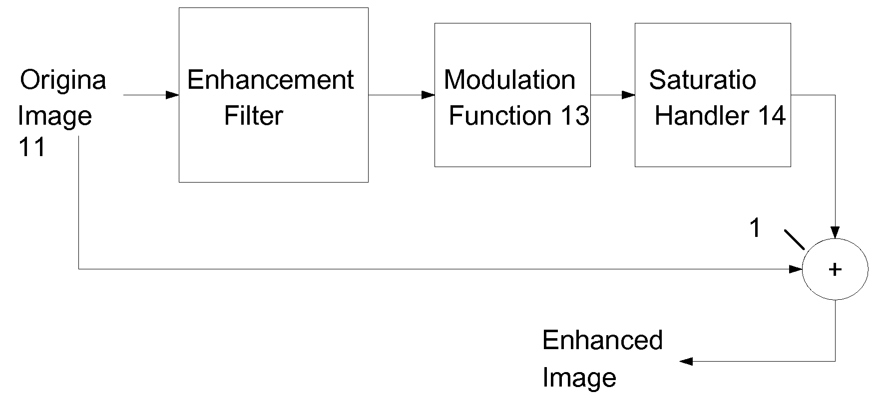
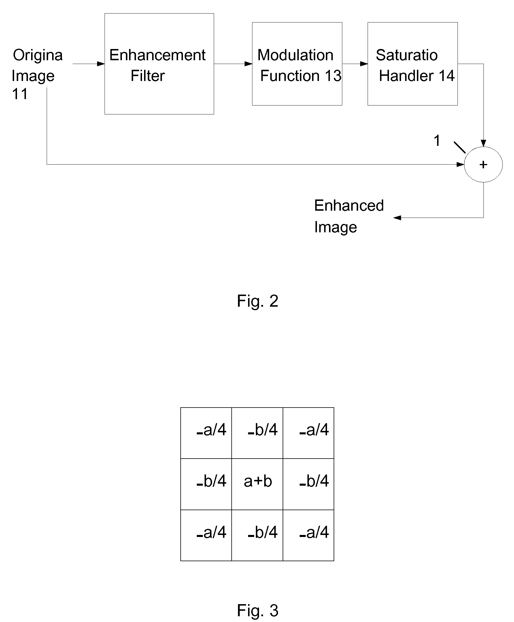
[0045] Referring to FIG. 2, which shows schematically an overview of an example of a method according to the invention, an original input image 11 is filtered by an enhancement filter 12. As will be explained further below, the enhancement filter 12 is a fixed, non-adaptive filter, i.e. the filter has fixed coefficients that do not change, and operates to output the high frequency component of the original image 11 in a single operational stage.

[0046] The output of the enhancement filter 12 is passed to a modulation function 13, which applies a gain g to the output of the enhancement filter 12. The nature of the preferred gain g will be discussed further below.

[0047] The output of the modulation function 13 is then passed to a saturation handler 14 which operates to avoid saturation of contrast in the enhanced image, again as will be discussed further below.

[0048] Then, the output of the saturation handler 14 is added back to the original image 11 in a summer 15 to obtain the enh...


PUM


Abstract

A method and apparatus adjusts the contrast of an input image formed of pixels. Each pixel in the input image has an input brightness level. At least some of the pixels in the output or enhanced image have an output brightness level that is different from their input brightness level. Brightness level data of the input image is filtered to obtain a high frequency component of the input image in a single operational stage. The high frequency component is amplified. The original image and the amplified high frequency component are summed to produce brightness level data of the output image.

Description

CROSS-REFERENCE TO RELATED APPLICATIONS [0001] This application claims the benefit of priority to U.S. application Ser. No. 60 / 806963, filed Jul. 11, 2006, the content of which is hereby incorporated by reference in its entirety for all purposes.FIELD OF INVENTION [0002] The present invention relates to a method and apparatus for adjusting the contrast of an image. BACKGROUND [0003] A number of techniques are known for adjusting the contrast of an image, particularly in order to improve the contrast and therefore visibility of the image and to increase depth perception. Contrast adjustment or enhancement of images, particularly digital images, is used in many fields, including enhancing the contrast of a digital image for display by a television receiver or other display device, for printing by a printer, in digital cameras, etc., etc. Contrast enhancement is used to improve the contrast in medical and other images. [0004] Global contrast enhancement techniques remedy problems that ...

Claims


Application Information

Patent Timeline
Patent Type & Authority Applications(United States)
IPC IPC(8): H04N5/57
CPCH04N5/208G06T5/004
Inventor ARICI, TARIKOZDEMIR, HUSEYINALTUNBASAK, YUCEL
Owner VESTEL ELEKTRONIK SANAYI & TICARET ANONIM SIRKETI
Why Eureka
Try Eureka