Display image enhancement apparatus and method using adaptive interpolation with correlation

Inactive Publication Date: 2005-07-28
TECHWELL
View PDF13 Cites 10 Cited by
  • Summary
  • Abstract
  • Description
  • Claims
  • Application Information

AI Technical Summary

Benefits of technology

[0013] An object of the present invention is to provide a system that is capable of converting an interlaced signal into a progressively scanned signal with improved quality of the displayed image, especially at low angle (i.e., near horizontal or near vertical) edges or at thin lines in the image.
[0014] Another object of the present invention is to provide a system that uses substantial angle observation (time based) and regional

Problems solved by technology

Interlacing video signals, however, reduce the vertical resolution of the displayed image.
However, some of the more recently developed display devices, such as some TFT-LCDs, do not support interlaced video signals.
Although this conversion method is simple and easy to implement, it often results in blurry images and causes zig-zagging, especially at lines or edges in the image at low angles (i.e., lines or edges that are close to being horizontal or vertical).
To a varying extent, these various deinterlacing techniques similarly suffer from the drawback of blurry images and/or zig-zagging.
In addition, some of these techniques are a

Method used


Image

  • Display image enhancement apparatus and method using adaptive interpolation with correlation
  • Display image enhancement apparatus and method using adaptive interpolation with correlation
  • Display image enhancement apparatus and method using adaptive interpolation with correlation

Examples


Embodiment Construction

[0036] Reference will now be made in detail to the preferred embodiments of the present invention, examples of which are illustrated in the accompanying drawings.

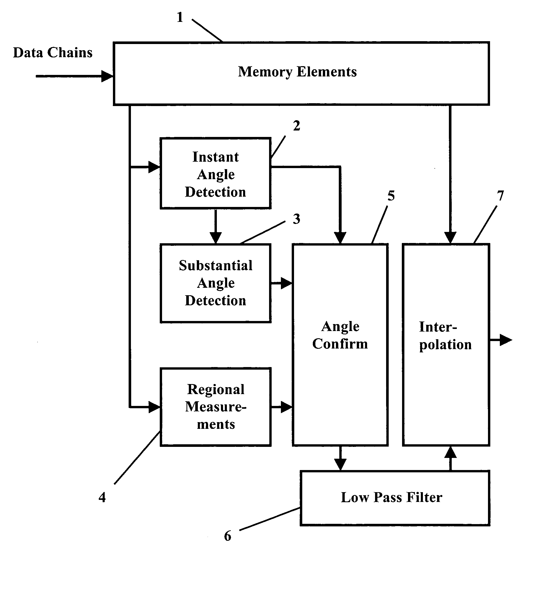
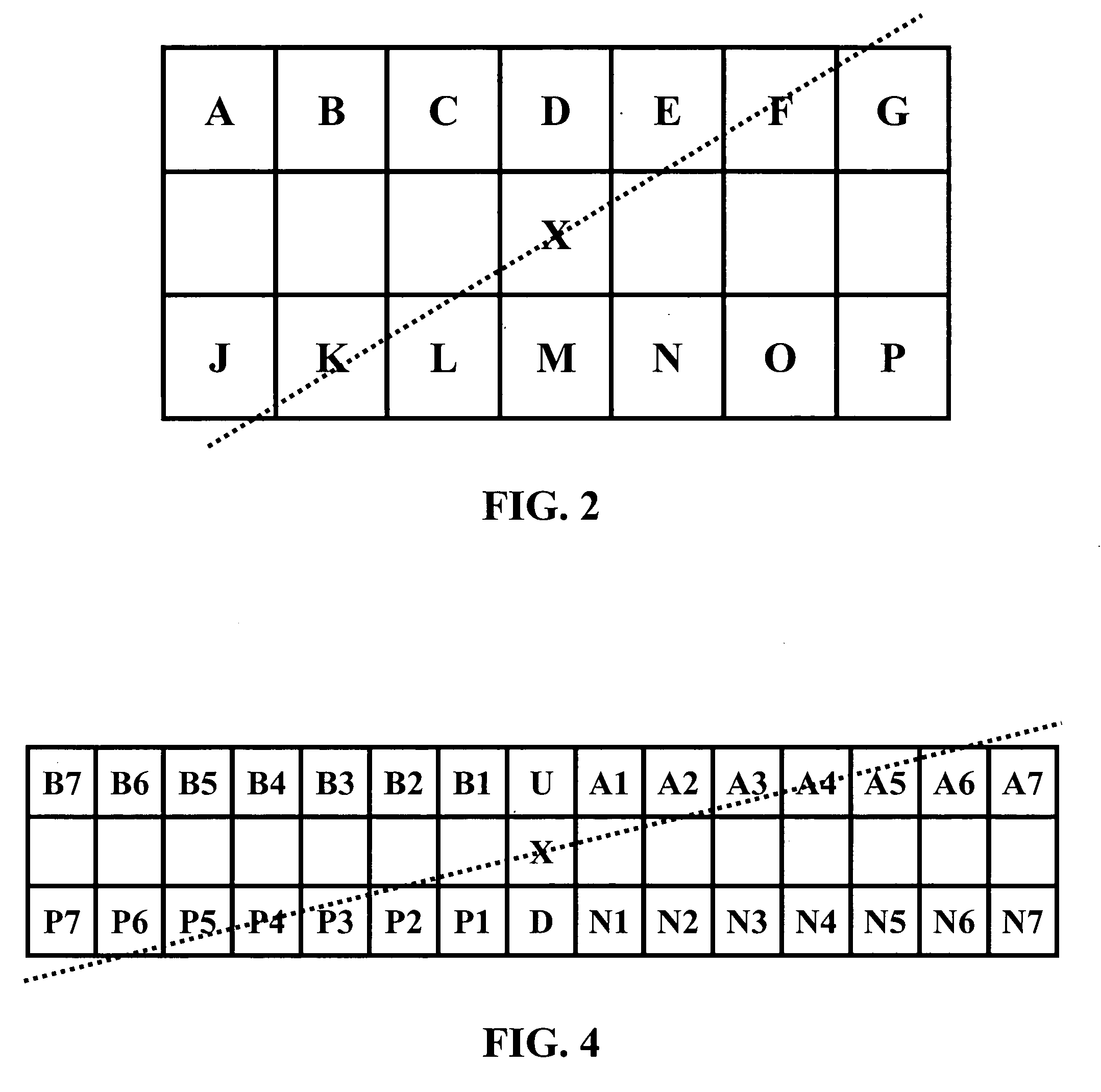
[0037] As shown in FIG. 3, the display image enhancement device according to an exemplary embodiment of the present invention includes memory elements 1 that continuously receive and store data chains, i.e., windows of input image pixel data. For example, the memory elements 1 may include a line buffer or another type of data storage element. In the exemplary embodiment shown in FIG. 4, values for each pixel in a window of 15 pixels by 2 pixels (pixels B7-A7 and P7-N7) are stored in memory elements 1, at a given time, for measurement and interpolation to determine the value for an additional pixel (pixel X) to be placed in the center of the window. Windows having sizes other than 15 by 2 may also be used. Also, depending on the requirements of the timing logic and any filtering logic, input image data can be pipe-lined and...


PUM


Abstract

A display image enhancement apparatus and method are disclosed for use in generating additional pixel data from input image data, where a window of input pixel data is used to generate data for an additional pixel to be placed substantially in the center of the window. The display image enhancement apparatus includes memory elements that is capable of receiving a chain of input pixel data and storing at least the window of input pixel data, where the window of input pixels includes a plurality of pixel pairs each of which respectively represents an angle of correlation. The display image enhancement apparatus also includes instant angle detection circuitry capable of receiving the input pixel data stored in the memory elements and determining an instant angle having the highest correlation based on differential values of at least some of the pixel pairs, where a differential value is the difference between the values of pixels in a pixel pair. The display image enhancement apparatus further includes substantial angle detection circuitry capable of determining a substantial angle having the highest correlation based on filtered differential values of at least some of the pixel pairs. Angle confirmation circuitry is provided to determine an interpolation angle based on the instant angle and the substantial angle. The display image enhancement apparatus employs an interpolator that is capable of determining the value of the additional pixel based on the values of pixels in the pixel pair corresponding to the interpolation angle.

Description

BACKGROUND OF THE INVENTION [0001] 1. Field of the Invention [0002] The present invention relates to a display image enhancement apparatus and method and, more particularly, to an apparatus and method for enhancing the quality of image on a display, such as a television, monitor, or other types of displays. [0003] 2. Discussion of the Related Art [0004] Typically, broadcast video signals (NTSC / PAL) are interlaced to reduce the bandwidth needed for broadcasting purposes. This allows for relatively high refresh rates, thereby reducing large area flickering. Interlacing video signals, however, reduce the vertical resolution of the displayed image. [0005] As shown in FIG. 1A, in an interlaced scan, a video signal is generated by alternatively scanning the odd lines and even lines of an image. In one refresh cycle, the odd lines of the image, shown as solid lines, are scanned. In the next refresh cycle, the even lines of the image, shown as dotted lines, are scanned. Then, the odd lines ...

Claims


Application Information

Patent Timeline
IPC IPC(8): G06K9/40G06T3/40H04N5/44H04N7/01
CPCH04N7/012G06T3/4007
Inventor PARK, SEONG H.MAH, JEREMYKANEKURA, HIROSHI
Owner TECHWELL
Why Eureka
Try Eureka