Stator for an electrical machine

a technology for stators and electrical machines, applied in the direction of basic electric elements, electrical apparatus, dynamo-electric machines, etc., can solve the problems of increasing production costs, and achieve the effects of reducing the leakage of magnetic flux between arms, and reducing the leakage of magnetic flux between stator elements

Inactive Publication Date: 2014-10-30
DYSON TECH LTD
View PDF8 Cites 6 Cited by
  • Summary
  • Abstract
  • Description
  • Claims
  • Application Information

AI Technical Summary

Benefits of technology

[0014]Since the turns of the outermost layer of the coil extends between opposite ends of the bobbin, the coil of each stator element may be maintained under tension. Additionally, magnetic flux leakage between stator elements may be reduced.
[0015]Each stator element may comprise a further bobbin and a further coil, the further coil being wound onto the further bobbin as a plurality of layers, each layer comprising a plurality of turns extending between opposite ends of the further bobbin. The outermost layer of the further coil then has a turn pitch greater than that of a lower layer. By providing a further coil about the core of each stator element, magnetic flux leakage may be further reduced.
[0016]The core may be c-shaped and comprise a back and a pair of arms extending from opposite ends of the back. The bobbin is then provided on one of the arms, and the further bobbin is provided on the other of the arms. Since each bobbin is provided on an arm of the core, magnetic flux leakage between the arms may be reduced.

Problems solved by technology

However, the provision of different bobbins increases the cost of production.

Method used


Image

  • Stator for an electrical machine
  • Stator for an electrical machine
  • Stator for an electrical machine

Examples


Embodiment Construction

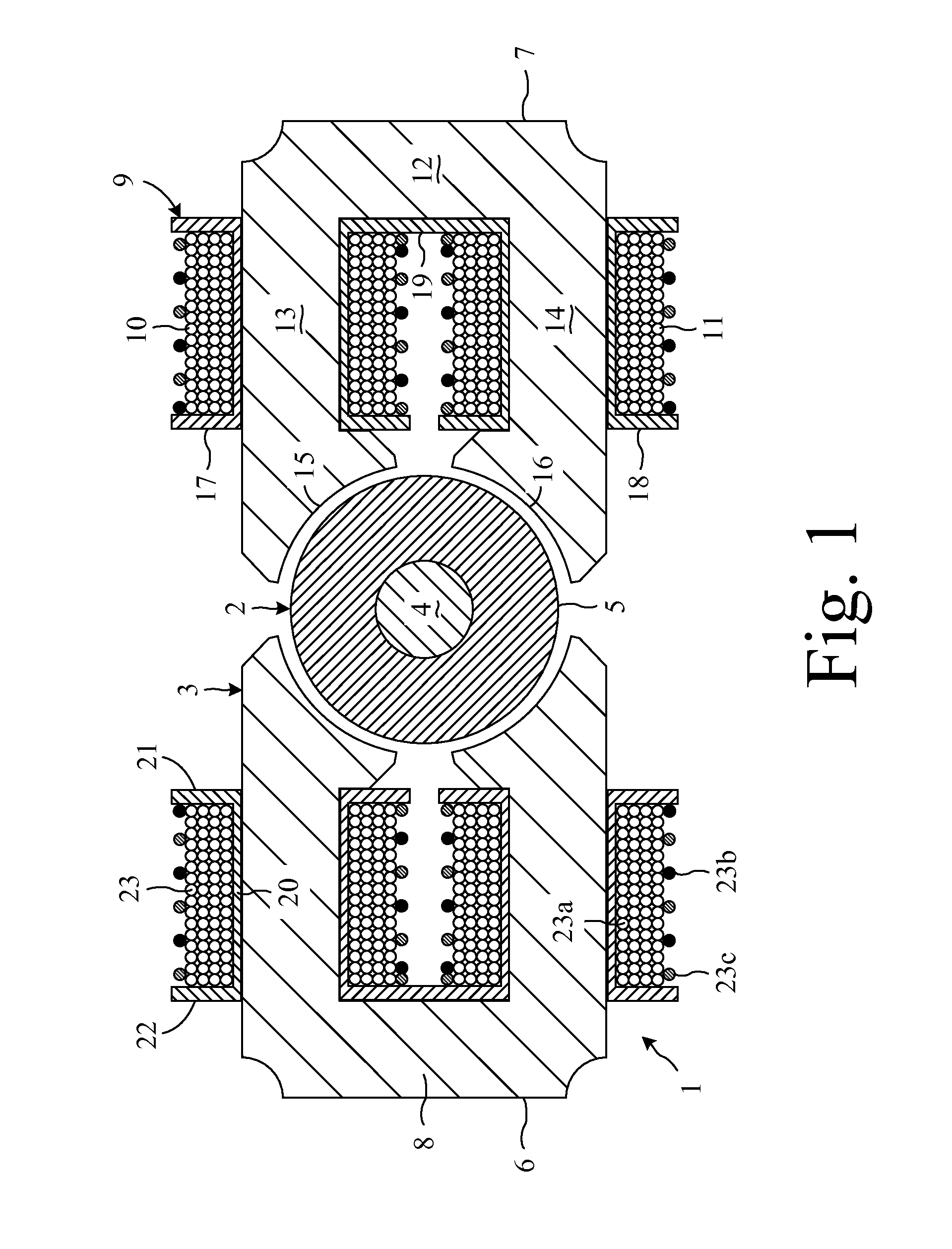
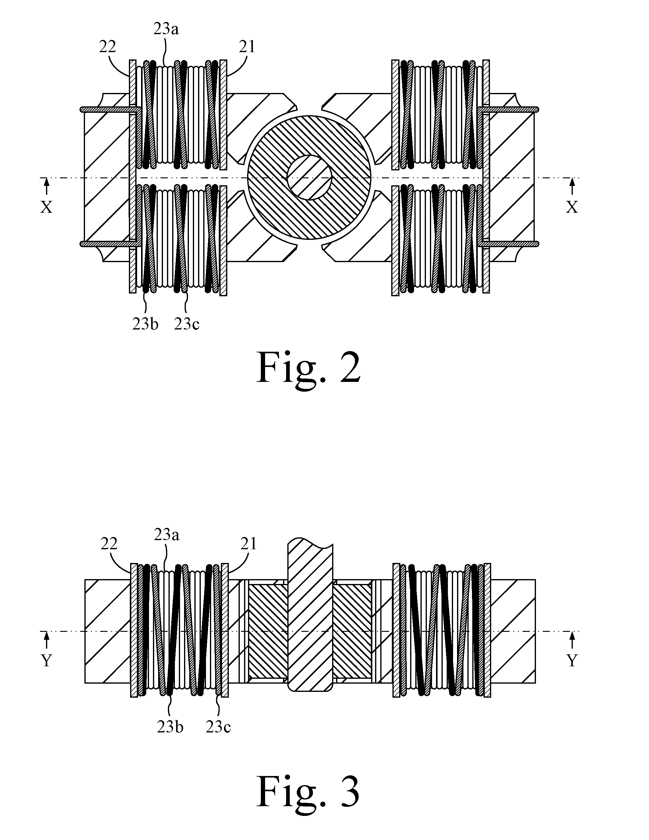
[0023]The electrical machine 1 of FIGS. 1 to 3 comprises a rotor 2 and a stator 3. The rotor 2 comprises a four-pole permanent magnet 4 supported on a shaft 5. The stator 3 comprises two stator elements 6,7 arranged on opposite sides of the rotor 2.

[0024]Each stator element 6,7 comprises a core 8, a bobbin element 9, and a pair of coils 10,11.

[0025]The core 8 is generally c-shaped and comprises a back 12 and two arms 13,14 that extend from opposite ends of the back 12. Each arm 13,14 extends toward the rotor 2 and has a free end that defines a pole face 15,16.

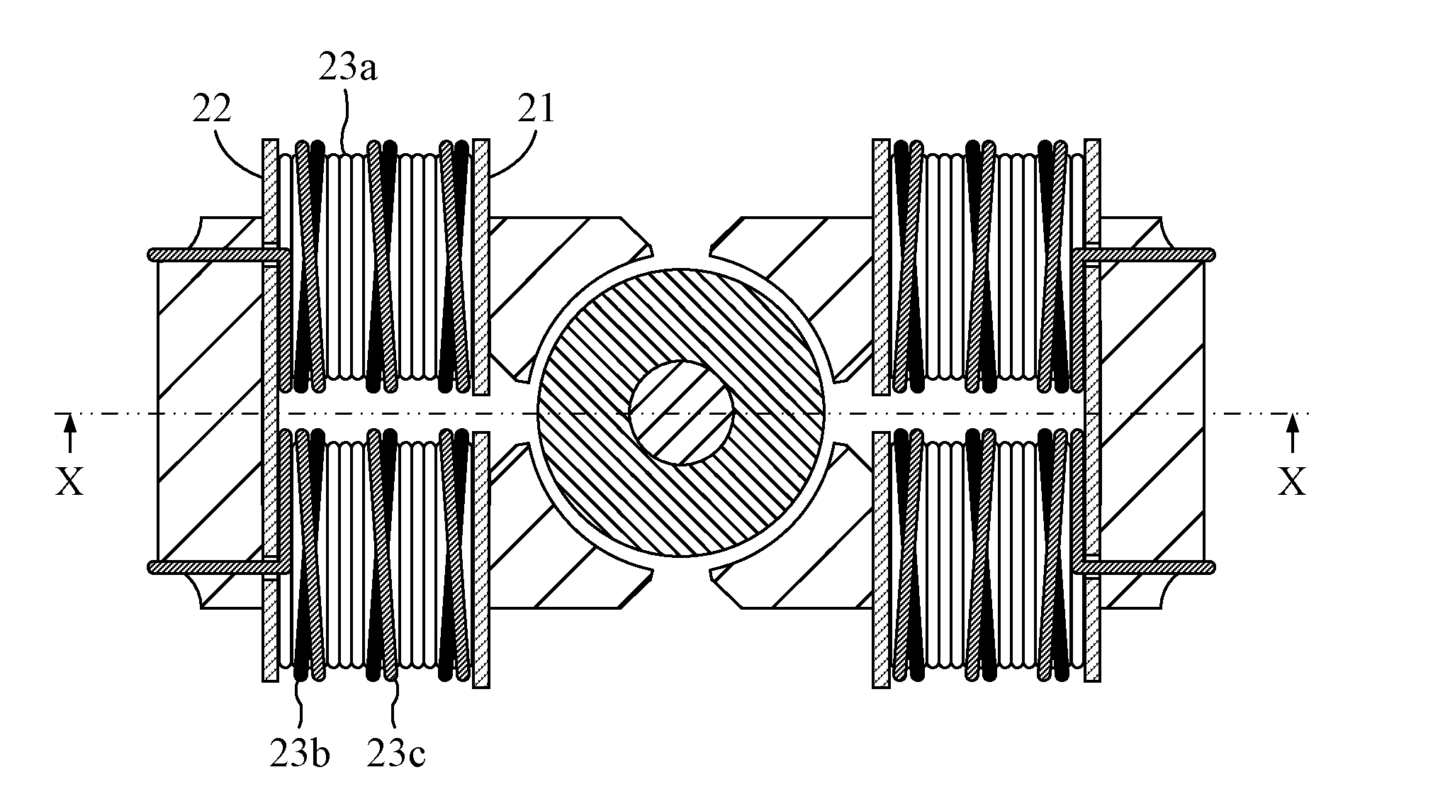
[0026]The bobbin element 9 comprises two bobbins 17,18 joined together by a bridging wall 19. Each bobbin 17,18 comprises a hollow tube 20, a front flange 21 and a rear flange 22, each flange 21,22 extending outwardly from an end of the tube 20. The hollow tube 20 of each bobbin 17,18 surrounds an arm 13,14 of the core 8. The front flange 21 is then proximal to the pole face 15,16, and the rear flange 22 is distal to the pole f...


PUM


Abstract

A stator comprising a coil wound onto a bobbin. The coil is wound as a plurality of layers, each layer comprising a plurality of turns that extend between opposite ends of the bobbin. The outermost layer has a turn pitch greater than that of a lower layer. Additionally, an electrical machine comprising the stator.

Description

REFERENCE TO RELATED APPLICATIONS[0001]This application is a national stage application under 35 USC 371 of International Application No. PCT / GB2011 / 052583, filed Dec. 23, 2011, which claims the priority of United Kingdom Application No. 1117770.6, filed Oct. 14, 2011, the entire contents of which are incorporated herein by reference.FIELD OF THE INVENTION[0002]The present invention relates to a stator for an electrical machine, and to an electrical machine incorporating the same.BACKGROUND OF THE INVENTION[0003]The coil of a stator is typically wound onto a bobbin. The size of the bobbin is generally defined such that, for a given wire diameter and number of turns, the first and last turns of the coil are located at an end of the bobbin. This then enables the free ends of the coil to be coupled to electrical terminals whilst maintaining the coil under tension.[0004]It may be necessary to use different coil configurations with the same stator. For example, the mains power supply in ...

Claims


Application Information

Patent Timeline
Patent Type & Authority Applications(United States)
IPC IPC(8): H02K3/18H02K3/34H02K1/08
CPCH02K3/18H02K3/345H02K1/08H01F41/086H02K15/095H02K21/185
Inventor LEAVER, MARK EDWARDGREETHAM, STEPHENLEE, KENNETH
Owner DYSON TECH LTD
Why Eureka
Try Eureka