
Magnetic stimulation device

a magnetic stimulation and magnetic pole technology, applied in the field of magnetic stimulation devices, can solve the problems of muscle function, difficult for patients to recover from paralysis, dysphagia (difficulty in swallowing), etc., to achieve the effect of avoiding complexity, reducing leakage of magnetic flux g between the magnetic poles from the tip region, and maintaining effective treatment constan

Pending Publication Date: 2022-08-11
IFG
View PDF0 Cites 0 Cited by
  • Summary
  • Abstract
  • Description
  • Claims
  • Application Information

AI Technical Summary

Benefits of technology

The present invention relates to a magnetic core for a device that generates a magnetic flux for treatment purposes. The technical effects of the invention include reducing leakage of magnetic flux from the tips of the device, maintaining a constant magnetic flux density, and suppressing temperature rise in the conductors. The shape of the legs in the device also contributes to suppression of temperature rise in the conductors. The device also includes a cooling space between the legs and conductors for better cooling. The conductors are divided into layers to level current densities and suppress local temperature rise. Overall, the invention aims to improve the effectiveness and comfort of magnetic treatment.

Problems solved by technology

Since paralysis persisting for a long period of time due to brain damage can cause a significant decrease in muscle function as a result of disuse syndrome, it is difficult for the patient to recover from the paralysis.
Dysphagia (difficulty in swallowing) as sequelae of cerebrovascular disorders or caused by aging is also becoming a social problem.
However, since a large current must be supplied to the magnetic stimulation device, the temperature of the device is likely to increase.

Method used


Image

  • Magnetic stimulation device
  • Magnetic stimulation device
  • Magnetic stimulation device

Examples


Embodiment Construction

[0075]Next, the present invention will be described in detail by way of embodiments. These embodiments are given for easy understanding by those skilled in the art. That is, it is to be understood that the present invention should not be limited only by these embodiments but should be limited only by the technical idea described in the entire specification of the present invention.

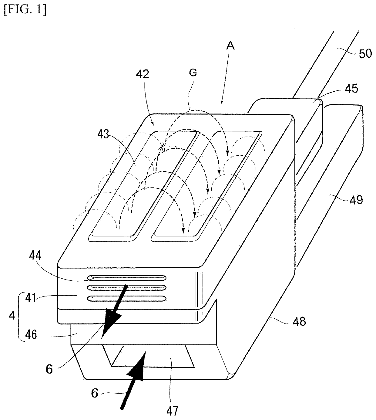
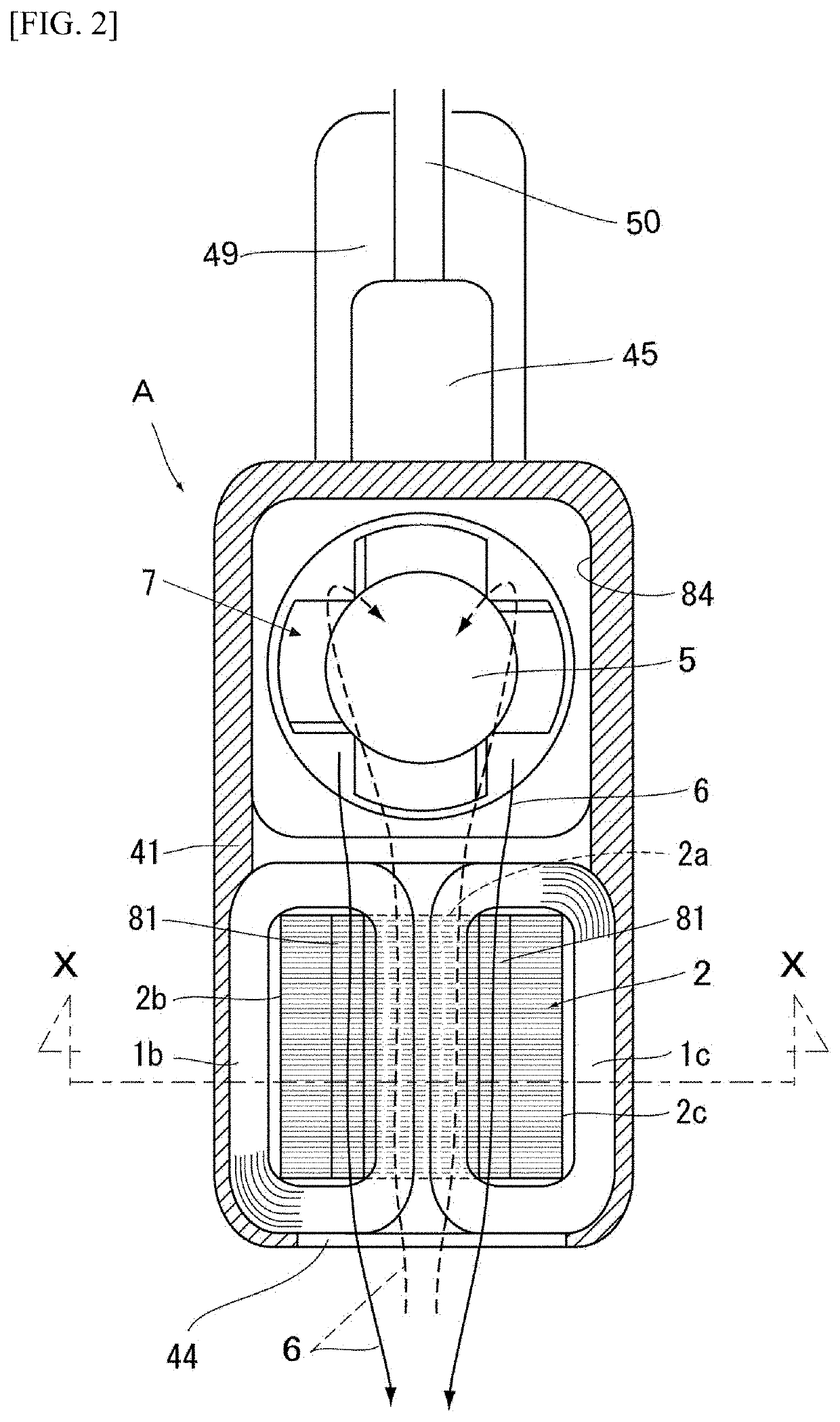
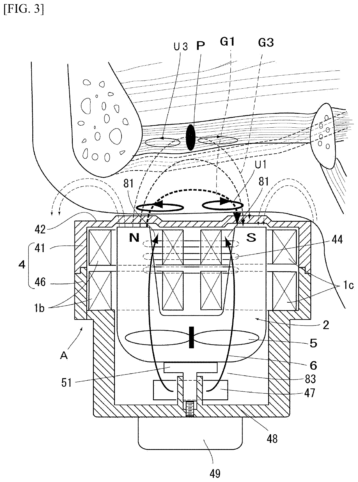
[0076]A continuous magnetic stimulation device A of the present invention includes conductors 1, a magnetic core 2, a casing 4, and a cooling mechanism 7. The conductors 1 are respectively wound around left and right legs 2b, 2c of the magnetic core 2 in a coil shape.

[0077]The magnetic core 2 is a U-shaped member and includes a cubic or cuboidal core body 2a and legs 2b, 2c extending axially symmetrically in the same direction from opposite ends of a surface of the core body 2a. The magnetic core 2 is a stack of thin sheets 3 to be described later.

[0078]The legs 2b, 2c each have such a shape that a cross-s...


PUM

PropertyMeasurementUnit
currentaaaaaaaaaa
temperatureaaaaaaaaaa
surface temperatureaaaaaaaaaa

Abstract

A magnetic stimulator includes a magnetic core, conductors, and a casing. The magnetic core includes a body portion, and leg parts that protrude in the same direction from the body portion. The conductors are wound in a coil manner respectively around the leg parts. The casing is a container for housing the magnetic core and the conductors. The leg parts of the magnetic core are formed such that cross-sectional areas thereof that are parallel to a plane which simultaneously crosses the leg parts gradually decrease from base parts on the body portion side toward tips.

Description

TECHNICAL FIELD[0001]The present invention relates to a magnetic stimulation device used for repeatedly applying magnetic stimulation to peripheral nerves in an affected region or motor areas of cerebral cortex to enhance motor function.BACKGROUND ART[0002]More than two million people are now suffering from paralysis of their limbs caused by cerebral strokes and spinal cord injuries, and the number of such paralytic patients is still increasing due to a change in the age structure of the Japanese population. Since paralysis persisting for a long period of time due to brain damage can cause a significant decrease in muscle function as a result of disuse syndrome, it is difficult for the patient to recover from the paralysis.[0003]Rehabilitation as a type of exercise therapy is considered to be the most important treatment to prevent disuse syndrome caused by hemiplegia or quadriplegia and to actively promote recovery of muscle function.[0004]Dysphagia (difficulty in swallowing) as se...

Claims


Application Information

Patent Timeline
Patent Type & Authority Applications(United States)
IPC IPC(8): A61N2/02A61N2/00H01F27/08H01F27/245H01F27/02
CPCA61N2/02A61N2/006H01F27/025H01F27/245H01F27/085H01F7/20H01F27/2876
Inventor MORI, HITOSHIYASHIMA, KENJIKAGAYA, HITOSHIIZUMI, SHINICHI
Owner IFG
Learn More