
RF device for synchrocyclotron

a technology of cyclotron and rf device, which is applied in the direction of magnetic resonance accelerator, electrical apparatus, electric discharge tube, etc., can solve the problems of complete breakdown of rf device, poor operation, and degradation of bearings by electro-corrosion, so as to reduce the cost, increase the reliability and/or durability of the assembly, and reduce the maintenance cost

Active Publication Date: 2014-10-30
ION BEAM APPL
View PDF8 Cites 18 Cited by
  • Summary
  • Abstract
  • Description
  • Claims
  • Application Information

AI Technical Summary

Benefits of technology

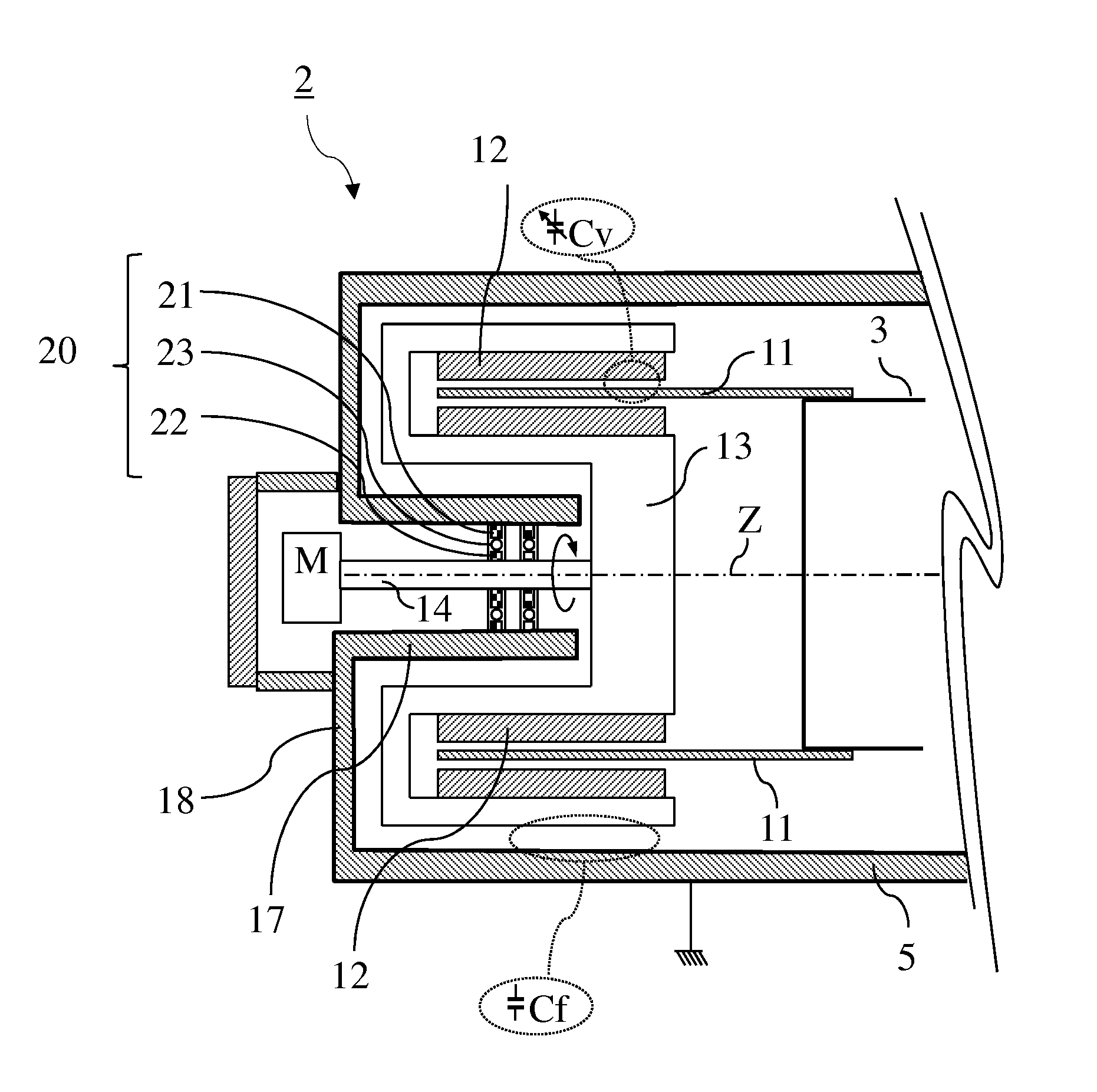
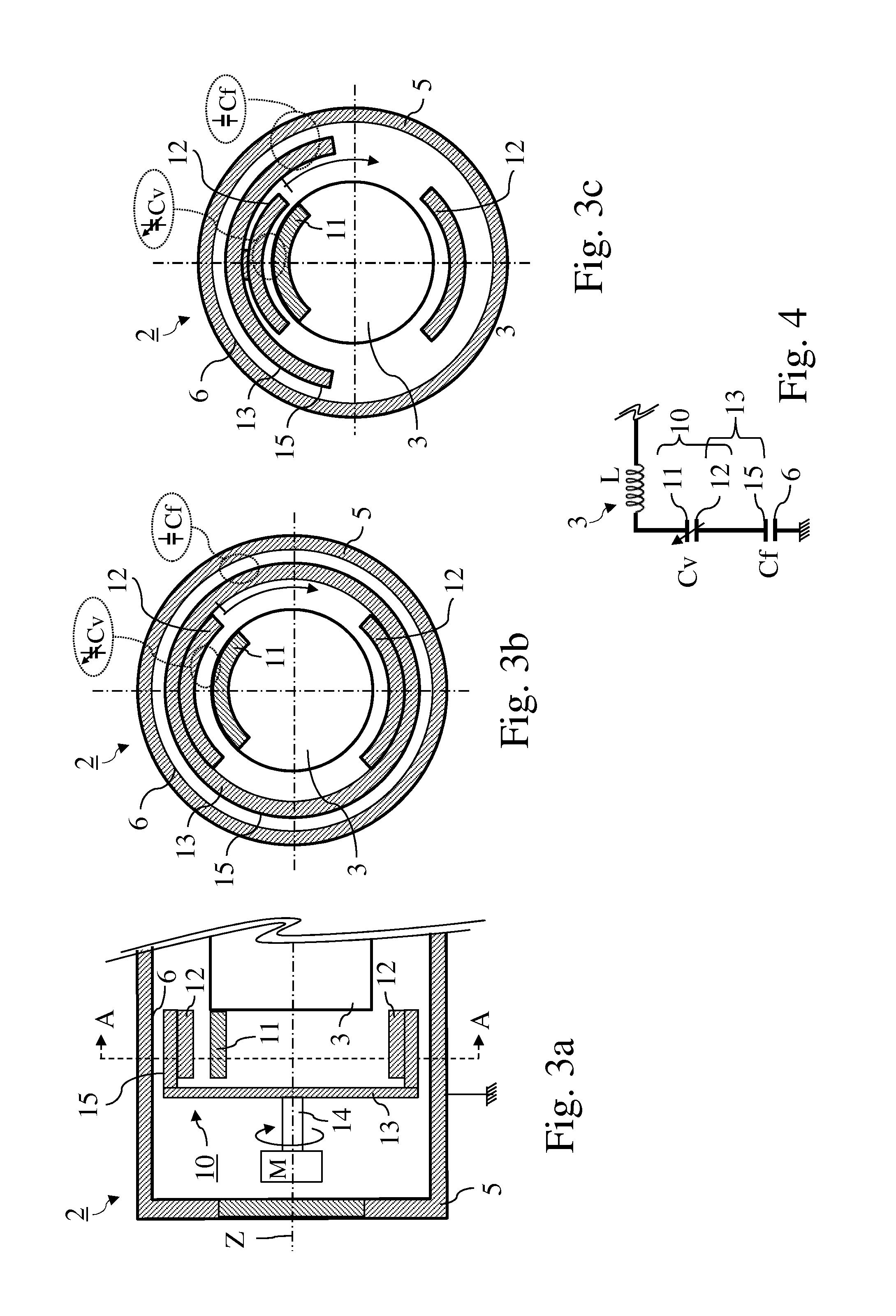
The invention is aimed at solving problems with current RF devices by providing a more reliable and durable solution. The combination of capacitive coupling and galvanic isolation through the bearings eliminates the need for sliding electrical contacts between the rotor and enclosure or pillar, which leads to a reduction in cost and bulkiness of the device. This also reduces maintenance requirements.

Problems solved by technology

One of the problems that they mention is the degradation of the sliding electrical contacts between the rotor and the conducting enclosure, possibly leading to poor operation, or indeed to a complete breakdown of the RF device.
Another problem, which is in fact one of the consequences of the degradation of these contacts, is the degradation by electro-corrosion of the bearings which support and guide, in rotation, the shaft of the rotor.
These bearings nonetheless continuing to be traversed by high RF currents, this does not satisfactorily solve the problems mentioned hereinabove.
These problems are accentuated by the fact that the RF devices for synchrocyclotrons which are undergoing development are of higher power and that their Rotcos will have to be capable of conducting RF currents of possibly up to for example 1000 A, under voltages of possibly up to for example 18000 V. The rotor will also revolve at higher speeds of possibly up to for example 7000 revolutions per minute.

Method used


Image

  • RF device for synchrocyclotron
  • RF device for synchrocyclotron
  • RF device for synchrocyclotron

Examples


Embodiment Construction

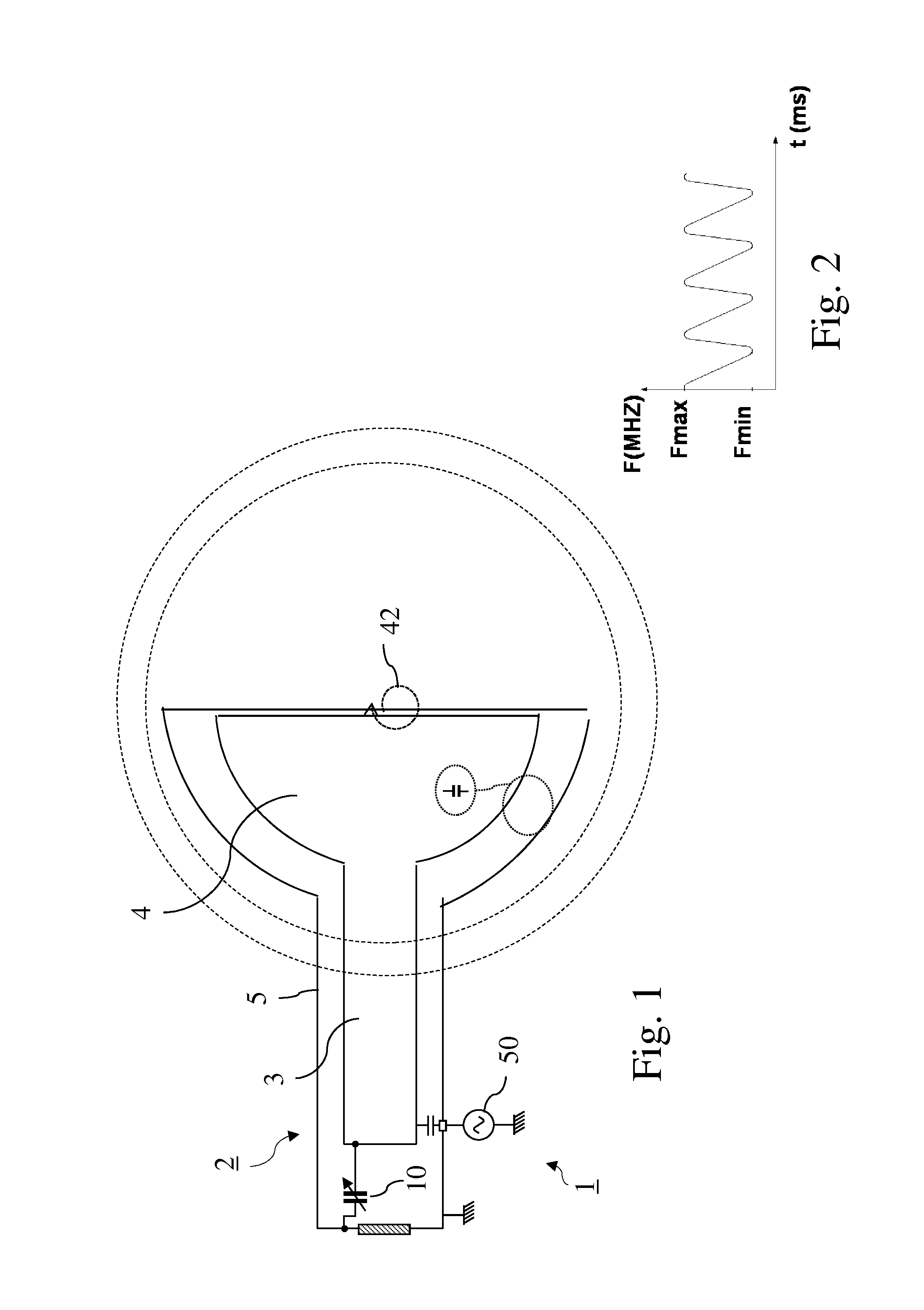
[0041]In order to show firstly briefly the known setting within which the invention lies, FIG. 1 represents in a schematic manner an RF device of a synchrocyclotron. This RF device (1) includes a resonant cavity (2) comprising:[0042]a conducting pillar (3) of which a first end is linked to an accelerating electrode (4) which will generate, when operating, an electric field so as to accelerate charged particles whose trajectory (42) in the synchrocyclotron is indicated by a dashed line in the figure,[0043]a conducting enclosure (5) surrounding the pillar (3),[0044]a rotary variable capacitor (10) (here represented by its electrical symbol) mounted in the conducting enclosure and comprising on the one hand at least one fixed electrode galvanically linked (for example welded or screwed) to a second end of the conducting pillar, the second end being opposite from the first end, and on the other hand a rotor comprising at least one moveable electrode linked electrically to the conducting...


PUM


Abstract

RF device (1) able to generate an RF acceleration voltage in a synchrocyclotron. The device comprises a resonant cavity (2) formed by a grounded conducting enclosure (5) and enveloping a conducting pillar (3) to a first end of which an accelerating electrode (4) is linked. A rotary variable capacitor (10) is mounted in the conducting enclosure at a second end of the pillar, opposite from the first end, comprising at least one fixed electrode (stator) (11) and a rotor (13) exhibiting a rotation shaft (14) supported and guided in rotation by galvanically isolating bearings (20), said rotor (13) comprising one moveable electrode (12) possibly facing the stator (11). When the shaft (14) rotates, the stator and the moveable electrode together form a variable capacitance whose value varies cyclically with time. The rotor (13) is galvanically isolated from the conducting enclosure (5) and from the pillar (3). The stator (11) is connected to the second end of the pillar (3) or to the conducting enclosure (5). The rotor is respectively coupled capacitively to the conducting enclosure or to the pillar. This makes it possible to dispense with sliding electrical contacts between the rotor and respectively the conducting enclosure or the pillar.

Description

FIELD OF THE INVENTION[0001]The present invention pertains to the field of radiofrequency (RF) resonators for synchrocyclotrons, and in particular to an RF device able to generate a voltage for accelerating charged particles in a synchrocyclotron, the RF device including a resonant cavity comprising:[0002]a conducting pillar of which a first end is linked to an accelerating electrode adapted to accelerate said particles,[0003]a conducting enclosure surrounding the conducting pillar,[0004]a rotary variable capacitor mounted in the conducting enclosure and comprising on the one hand at least one fixed electrode linked galvanically to a second end of the conducting pillar, the second end being opposite from the first end, and on the other hand a rotor comprising at least one moveable electrode, the at least one fixed electrode and the at least one moveable electrode together forming a variable capacitance able to cause a resonant frequency of the cavity to vary over time, the rotor bei...

Claims


Application Information

Patent Timeline
IPC IPC(8): H05H7/02H05H13/02
CPCH05H7/02H05H2007/025H05H13/02
Inventor ABS, MICHELAMELIA, JEAN-CLAUDE
Owner ION BEAM APPL
Learn More