
Optical image stabilizer

a stabilizer and optical technology, applied in the field of telescopes, can solve the problems of aggravating the resolution of optical images, deteriorating measurable deteriorations in the quality of optical images of objects, so as to reduce the cost and simplify the mechanism

Active Publication Date: 2014-10-30
KAMAKURA KOKI
View PDF5 Cites 9 Cited by
  • Summary
  • Abstract
  • Description
  • Claims
  • Application Information

AI Technical Summary

Benefits of technology

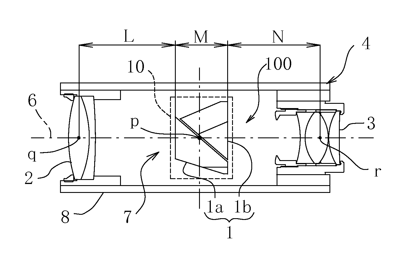
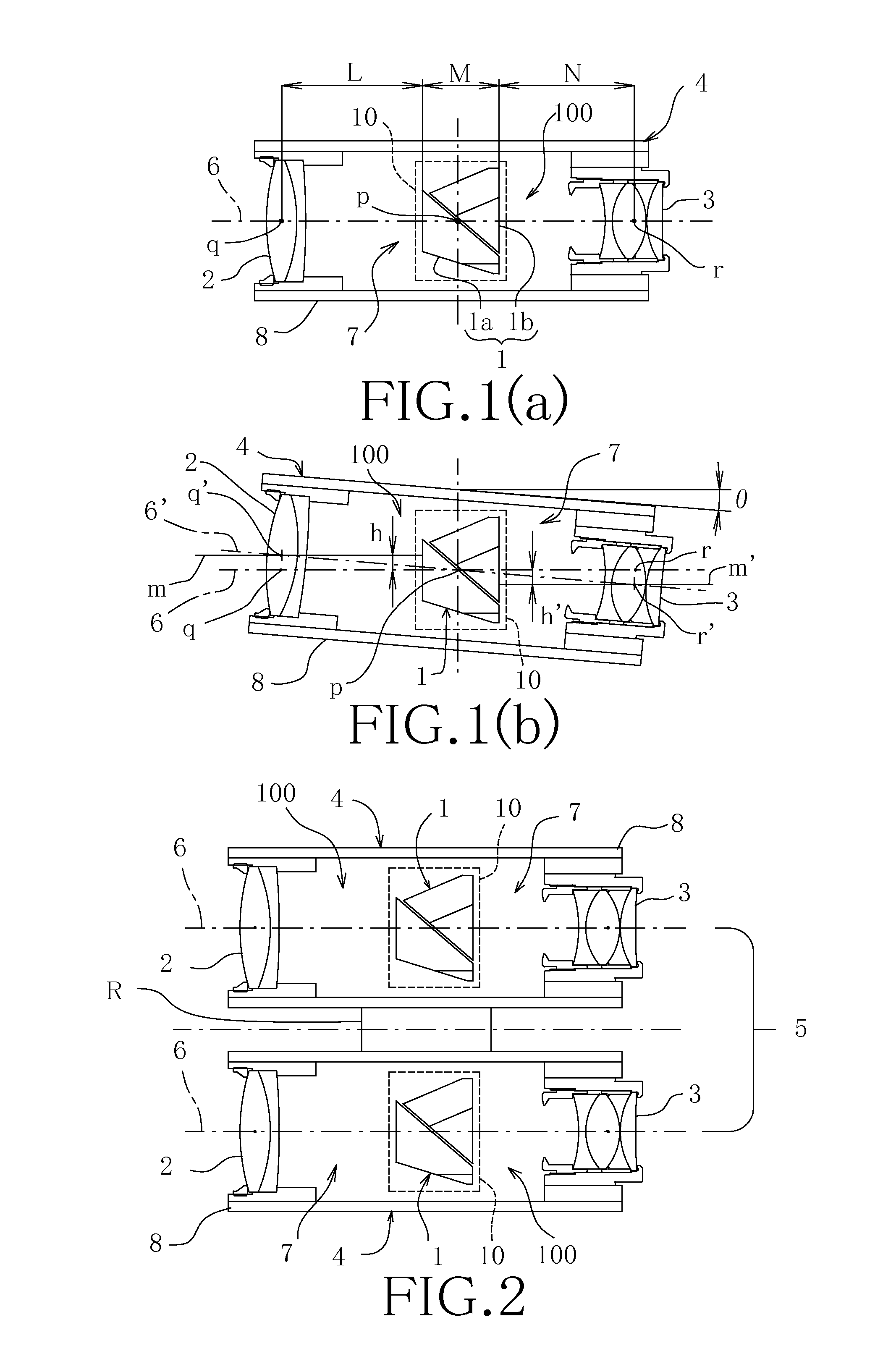
The present invention provides an optical image stabilizer for telescopic optical instruments such as binoculars and monocular devices. It uses a rotating gimbal system with an erect prism that is located between the objective lens and eyepiece lens. This system compensates for horizontal vibrations and deteriorations in image quality caused by unsteady hands or external vibrations. The optical image stabilizer is designed to be cost-effective, compact, and easy to use. It is adaptable to a wide range of telescopic optical instruments.

Problems solved by technology

Such the hand-shakings cause the telescopic optical instrument to develop fluctuations in the angle of a beam of light emanating from the object under observation relative to an optical axis of the optical system of the optical instrument (which is hereinafter referred to as the “telescopic optical system”), resulting in deteriorations in the quality of an optical image of the object under observation.
These deteriorations may include at least blurring of the telescopic optical image, or image-shakings (shakings of an image responding to hand-shakings which means vibrations of the hand-held telescopic optical instrument), and aggravation of resolution of the optical images, among others.
Even if vibrations imparted or applied to the optical instrument are small in amplitude, measurable deteriorations are induced in the quality of an optical image of an object under observation because that the optical instrument, in the case of monocular or binocular devices, has only a narrow field of view and that an image formed by an objective lens is magnified through an eyepiece lens.
At the same time, although the optical image stabilizer disclosed in Document II has an effect on miniaturizing the telescopic optical systems of the binoculars which has a pair of erect prisms, nevertheless, since the rotary motor for rotating gimbal shafts and the potentiometer need a relatively large space for installation, the optical image stabilizer is hardly suitable for miniaturization of a monocular having a single erect prism in its telescopic optical system.
Further, the optical image stabilizers disclosed in Document III or IV has the advantage of being rendered small in mechanism and, however, is disadvantageously limited in availability because of a small range of correctable vibrations.

Method used


Image

  • Optical image stabilizer
  • Optical image stabilizer
  • Optical image stabilizer

Examples


Embodiment Construction

[0012]It is a purpose of the present apparatus to provide an optical image stabilizer for a telescopic optical instrument, typified by monocular devices and binoculars, having a telescopic optical system with an erect prism which is mounted on miniaturized, weight-saved, and inexpensively constituted gimbal means in a position between an objective lens and an eyepiece lens. This enables the structure to be capable of rotating on two axes of rotation orthogonal to each other and intersecting with an optical axis of the telescopic optical system at a right angle, thereby compensating for deteriorations in the quality of a telescopic optical image induced by horizontal vibrations which may be caused by vibrations of the vehicle (automobile, aircraft, or boat, for example) in which the user is riding, or even by unsteady hands of the user.

[0013]The above purpose is accomplished by an optical image stabilizer for telescopic optical instruments of the types discussed herein, which have a ...


PUM


Abstract

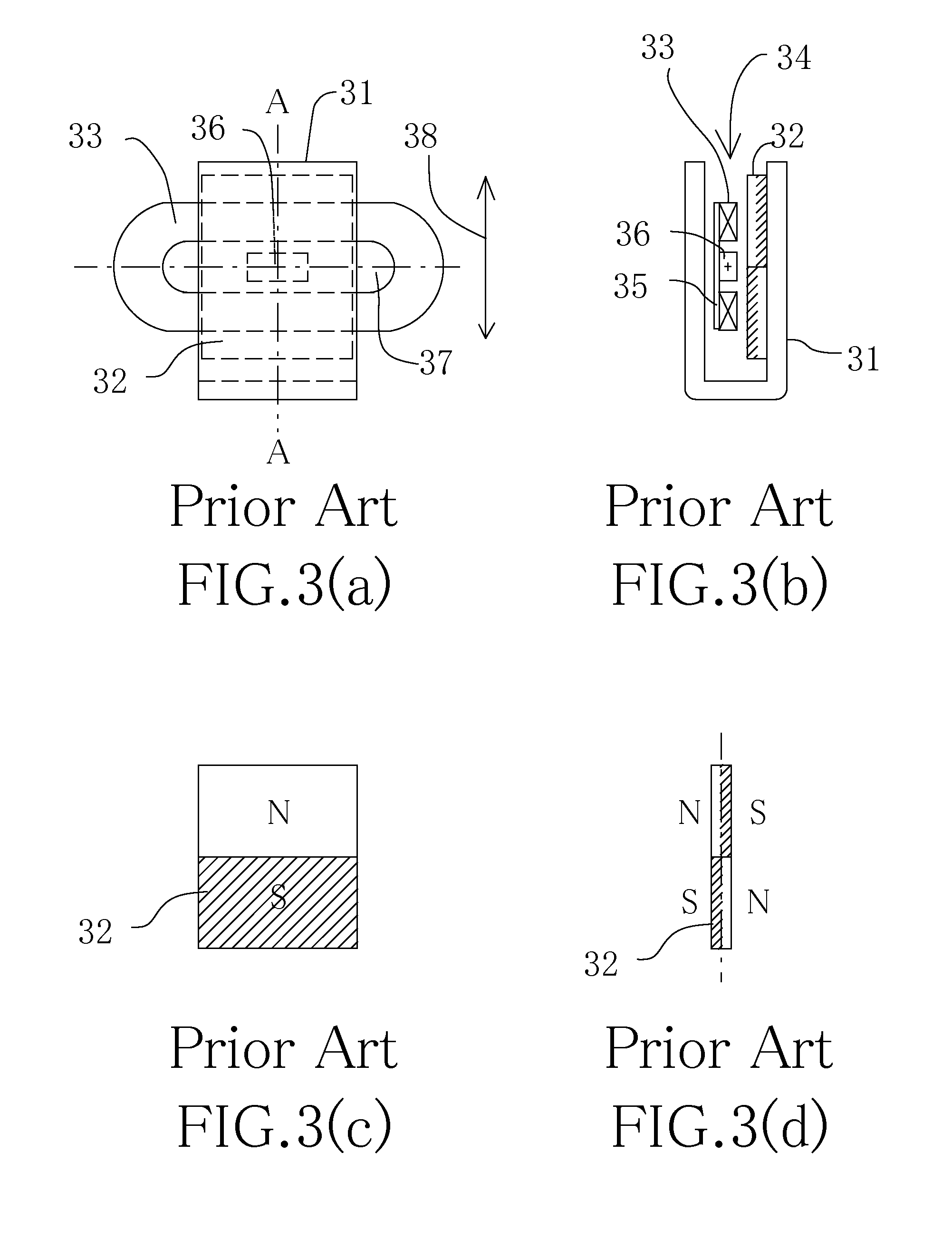
An optical image stabilizer for a telescopic instrument having an objective lens, an erect prism, and an eyepiece lens arranged in this order which is capable of compensating for image deteriorations of an observed image due to external vibrations. The optical image stabilizer has a gimbal device mounted on a telescope housing, an external gimbal frame rotatably mounted on the gimbal casing, and an internal gimbal frame with the erect prism fixed thereto. Voice coil motors are provided for rotating the external and the internal gimbal frames. One of the voice coil motors has a coil disposed on the circuit board and a permanent magnet disposed on either one of the external and the internal gimbal frames oppositely to the coil. The remaining voice coil motor has a coil disposed on the circuit board and a permanent magnet disposed on the other gimbal frame oppositely to the coil.

Description

FIELD OF INVENTION[0001]The present apparatus relates generally to telescopic optical instruments and more particularly to an optical image stabilizer for instruments, such as monocular and binocular devices.BACKGROUND OF THE INVENTION[0002]When holding a telescopic optical instrument, as typified by a monocular device or binoculars, with hands, and operating it to make observations of an object and, in particular, when operating a hand-held telescopic optical instrument in a flying aircraft or a moving vehicle, the instrument encounters hand-shakings arising from vibrations (oscillating angular displacements or motions of the longitudinal axis of an aircraft or a vehicle due to yawing and pitching) of the flying aircraft or the moving vehicle imparted to a housing of the optical instrument. Such the hand-shakings cause the telescopic optical instrument to develop fluctuations in the angle of a beam of light emanating from the object under observation relative to an optical axis of ...

Claims


Application Information

Patent Timeline
IPC IPC(8): G02B27/64
CPCG02B27/646G02B23/02
Inventor ANDO, KUNIOKATO, MASASHIITOH, HARUOMIYAJI, KAZUYA
Owner KAMAKURA KOKI
Learn More