Image encoding method and apparatus and image decoding method and apparatus based on motion vector normalization

a motion vector and image technology, applied in the field of encoding and decoding of images, can solve the problems of inaccurate estimation of the actual motion of an object in an image, inability to accurately reflect the actual motion of an object, and high probability

Active Publication Date: 2014-10-30
SAMSUNG ELECTRONICS CO LTD +1
View PDF1 Cites 10 Cited by
  • Summary
  • Abstract
  • Description
  • Claims
  • Application Information

AI Technical Summary

Benefits of technology

[0008]Exemplary embodiments relate to obtaining a larger merged block by merging blocks included in the same object and estimating a motion vector based ...

Problems solved by technology

Since a motion estimation method, such as a BMA, estimates a motion vector that minimizes a sum of absolute difference (SAD), it is highly likely that actual motion of an object in an image is not accurately estimated.
For example, while motion-estimating a block included in a homogeneous object, since it is highly likely that a plurality of blocks similar to a block that is motion-estimated may exist in a previous frame, a motion vector may not...

Method used


Image

  • Image encoding method and apparatus and image decoding method and apparatus based on motion vector normalization
  • Image encoding method and apparatus and image decoding method and apparatus based on motion vector normalization
  • Image encoding method and apparatus and image decoding method and apparatus based on motion vector normalization

Examples


Embodiment Construction

[0031]Hereinafter, one or more exemplary embodiments will be described in detail with reference to accompanying drawings.

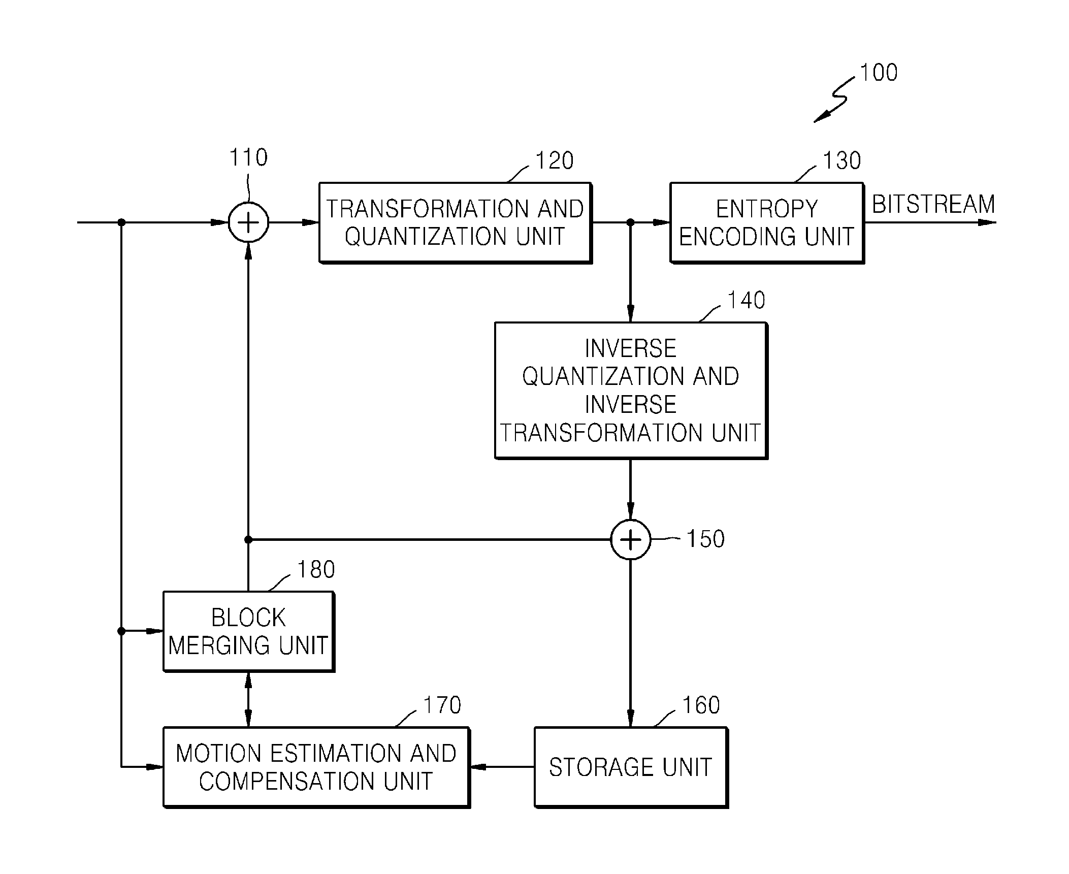
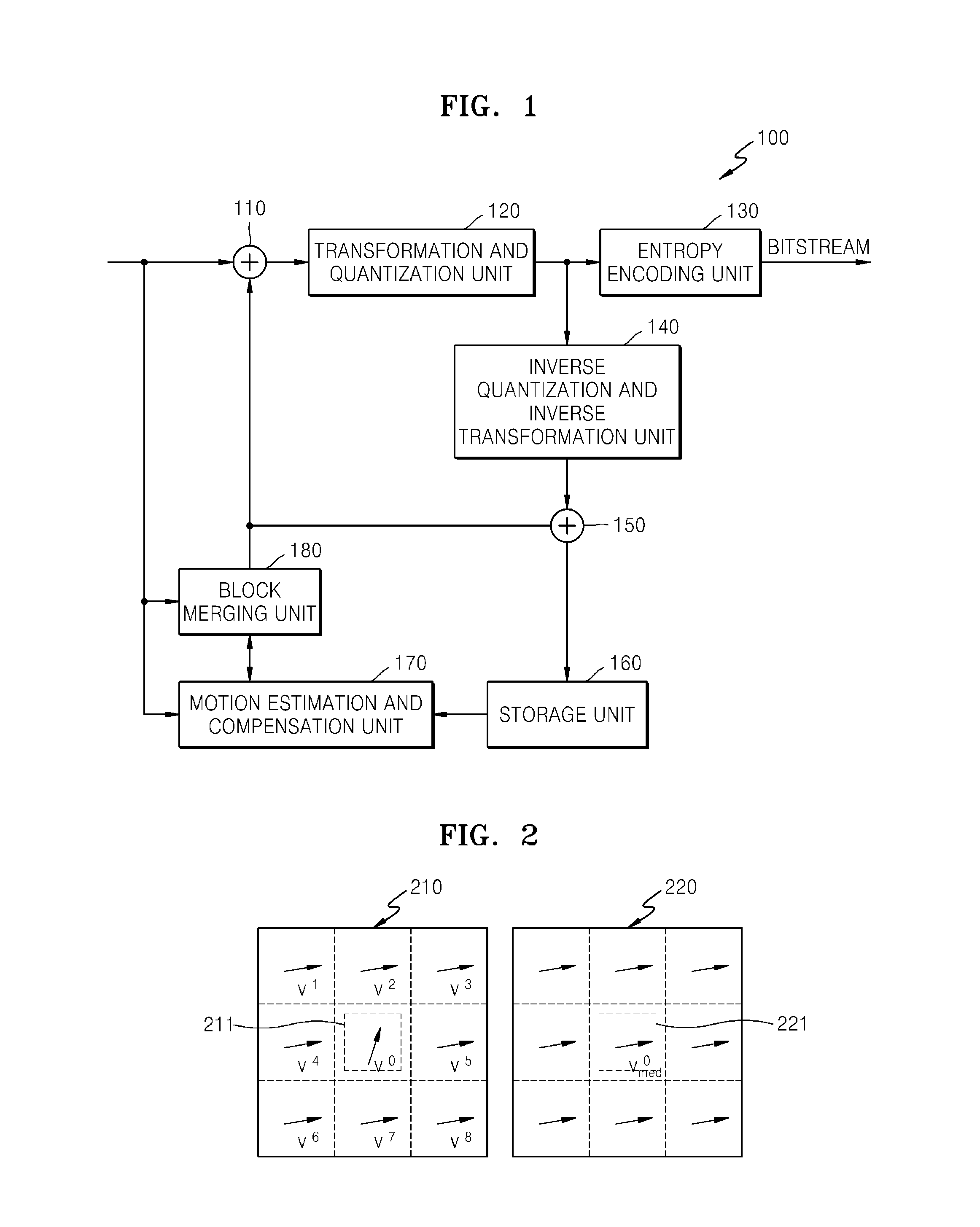
[0032]FIG. 1 is a block diagram of a structure of an image encoding apparatus, according to an exemplary embodiment. Referring to FIG. 1, an image encoding apparatus 100 includes a subtractor 110, a transformation and quantization unit 120, an entropy encoding unit 130, an inverse quantization and inverse transformation unit 140, an adder 150, a storage unit 160, a motion estimation and compensation unit 170, and a block merging unit 180. An intra prediction unit that is not shown may generate an estimation value of each block by performing intra prediction in units of blocks in an intra prediction mode.

[0033]The motion estimation and compensation unit 170 splits an input image into blocks having a predetermined size, and obtains a motion vector of each block by performing motion estimation on each block. Hereinafter, a block described herein may indicate one of a...


PUM


Abstract

Provided are an image encoding method and apparatus, and an image decoding method and apparatus. The image encoding method includes: obtaining a variation of a motion estimation error with respect to a homogeneity degree of a motion vector according to mergence, based on a motion vector of each of merged blocks obtained by merging adjacent blocks, motion vectors of the adjacent blocks included in each of the merged blocks, and motion vectors of neighboring blocks of each of the merged blocks; and determining, based on the obtained variation, a merged block having a smallest variation from among the merged blocks and whether to merge the adjacent blocks included in the determined merged block.

Description

RELATED APPLICATIONS[0001]This is a continuation application of PCT / KR2013 / 000192 filed on Jan. 9, 2013 which claims the benefit of U.S. Provisional Application 61 / 584,386, filed on Jan. 9, 2012, in the United States Patent and Trademark Office, the disclosures of which are hereby incorporated herein in their entirety by reference.BACKGROUND[0002]1. Field[0003]Exemplary embodiments relate to encoding and decoding of an image, and more particularly, to a method and apparatus for encoding an image and a method and apparatus for decoding an image by using a motion vector of a merged block obtained by merging blocks. Also, exemplary embodiments relate to a method and apparatus for encoding an image and a method and apparatus for decoding an image by splitting an image in units of objects, and performing motion estimation and compensation in the units of objects.[0004]2. Related Art[0005]In an image compression method, such as MPEG-1, MPEG-2, MPEG-4, or H.264 / MPEG-4 advanced video coding...

Claims


Application Information

Patent Timeline
IPC IPC(8): H04N19/51
CPCH04N19/00684H04N19/521H04N19/52H04N19/543H04N19/139H04N19/176H04N19/119H04N19/147H04N19/192H04N19/50H04N19/513
Inventor PARK, SEUNG-HOKIM, JAE-HYUNPARK, SE-HYEOKPARK, HYUN-WOOKLIM, HYUNG-JUN
Owner SAMSUNG ELECTRONICS CO LTD
Why Eureka
Try Eureka