Image-Guided Radiotherapy

a radiotherapy and guided beam technology, applied in the field of image-guided radiotherapy, can solve the problems of poor image quality, poor contrast between human tissue types, and the potential to cause harm to the normal healthy tissue around the lesion, and achieve the effect of limiting the cross-sectional area of the beam

Active Publication Date: 2014-10-30
ELEKTA AB
View PDF2 Cites 13 Cited by
  • Summary
  • Abstract
  • Description
  • Claims
  • Application Information

AI Technical Summary

Benefits of technology

[0012]In its first aspect, the present invention therefore provides a radiotherapy apparatus, comprising a rotatable gantry, supporting a source of therapeutic radiation and a source of diagnostic radiation, the two sources being rotationally (or angularly) spaced apart around a rotation axis of the gantry, with at least one collimator associated with the source of therapeutic radiation and arranged to limit the cross-sectional area of a beam produced by that source, a control means arranged to conduct a treatment fraction using the apparatus by causing the apparatus to i. acquire images of a patient using the source of diagnostic radiation, ii. retain those images at least temporarily, iii. subsequently, after further rotation of the gantry, select a retained image acquired when the source of diagnostic radiation was at a rotational position corresponding to the instantaneous rotational position of the source of therapeutic radiation, and iv. control the beam relative to the patient (such as by adjusting the collimator or moving a patient support) using information derived from the selected image.

Problems solved by technology

Clearly, the beam has the potential to cause harm to the normal healthy tissue around the lesion, as well as to the tumour itself.
However, this changes with time and between treatments.
Such diagnostic imaging needs a lower energy x-ray source in order to provide high quality images, typically in the range of up to 125 keV, rather than the high-energy (5 MeV) beam used for treatment which can be used for imaging, but provides very poor contrast between human tissue types.
However, as noted the image quality is poor due to a marked lack of contrast.
However, these are an indirect measure of the tumour position and hence of lower accuracy.

Method used


Image

  • Image-Guided Radiotherapy
  • Image-Guided Radiotherapy
  • Image-Guided Radiotherapy

Examples


first embodiment

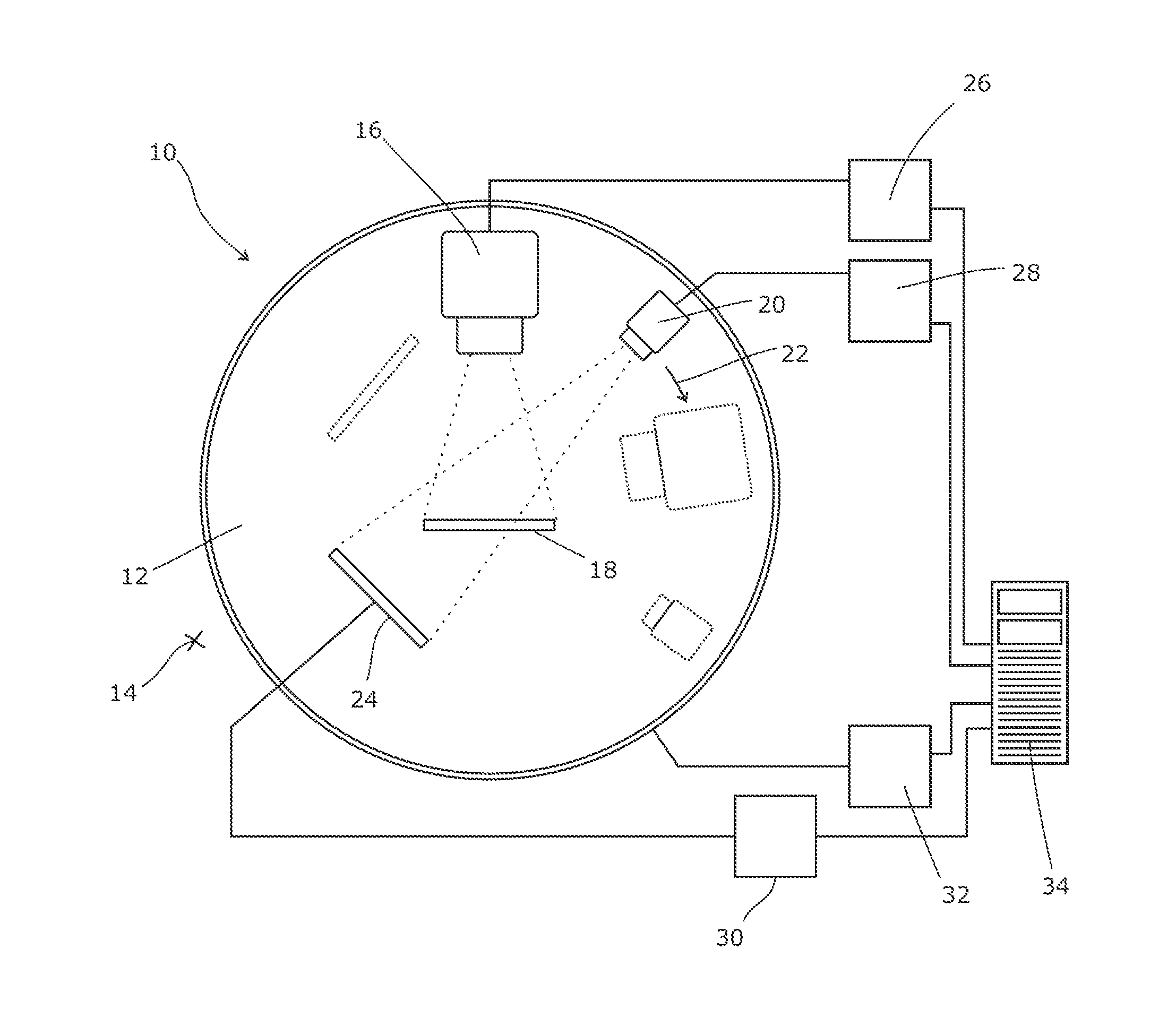
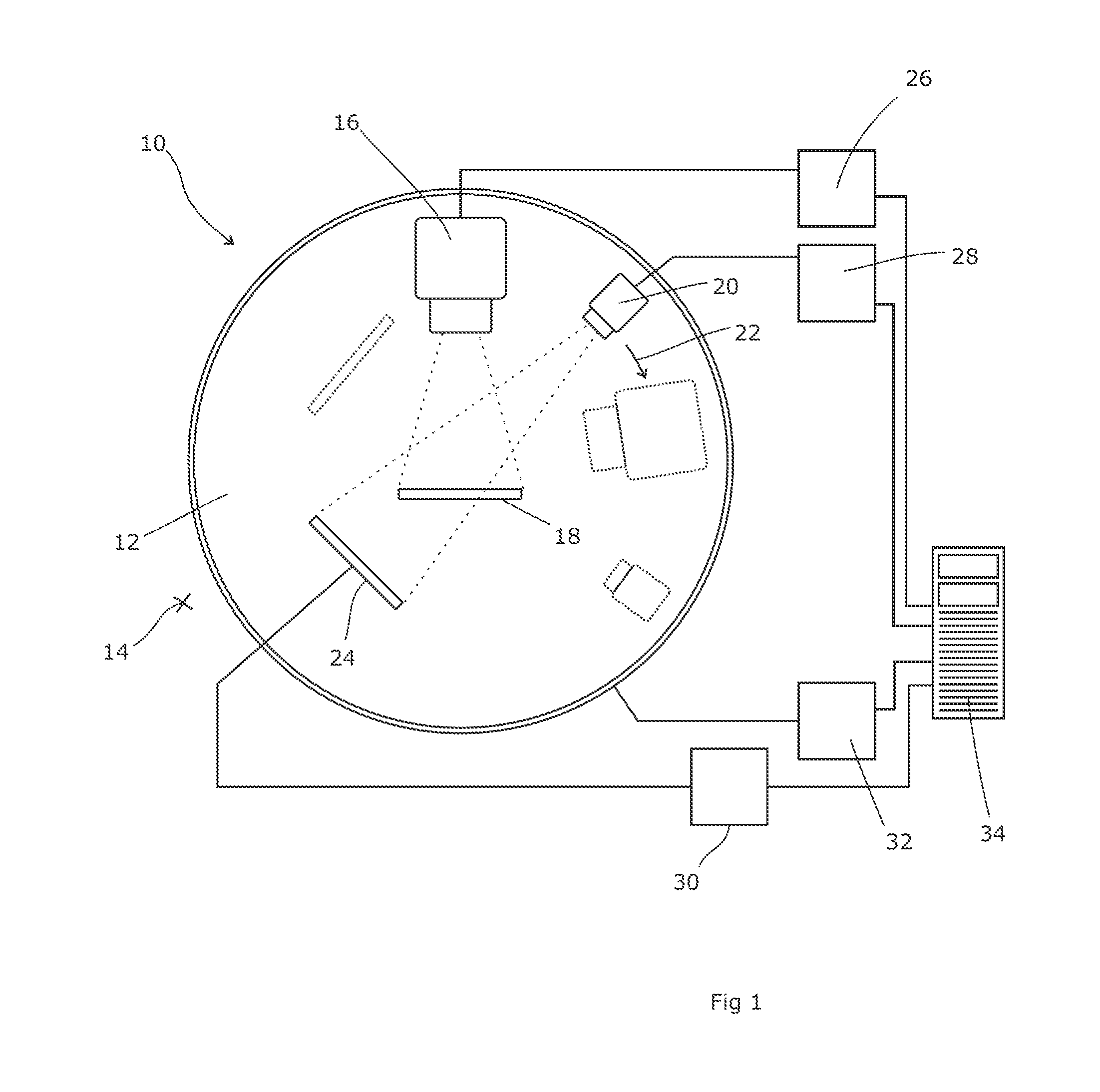
[0026]Referring to FIG. 1 which shows the first embodiment, a radiotherapy apparatus 10 comprises a support 12 which is rotatable about a central horizontal axis. Usually, the bulk of the support 12 is concealed behind a wall or false wall or covers 14 through which the support projects. A gantry projects from the support 12 and carries a therapeutic head 16 which produces a high-energy beam suitable for therapeutic purposes, directed toward the central horizontal axis. To create the beam, a linear accelerator is located within the support 12 and the gantry, ending in the therapeutic head 16. A relativistic beam of electrons from the accelerator is directed onto an x-ray target to produce a beam of high-energy x-rays in the appropriate direction. This is then filtered if necessary, such as with a flattening filter, and collimated by block collimators and multi-leaf collimators to create a therapeutically useful beam.

[0027]A patient table 18 is provided, just below the central horizo...

second embodiment

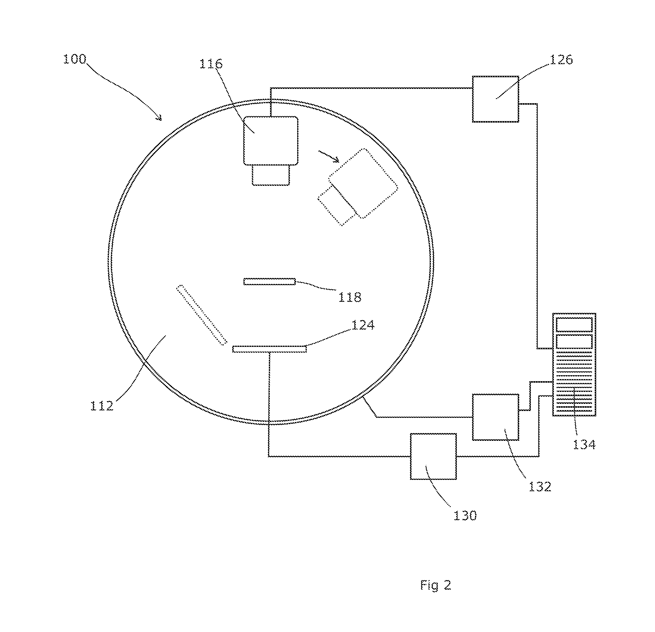
[0035]The second operating method could be put into effect using the apparatus described with reference to FIG. 1. Alternatively, it could use the apparatus of the second embodiment shown in FIG. 2. This radiotherapy apparatus 100 comprises a support 112, rotatable about a central horizontal axis, generally the same as the support 12 of FIG. 1. A single head 116 produces either a high-energy beam suitable for therapeutic purposes, or (selectably) a low-energy diagnostic beam of up to about 125 keV in energy, suitable for producing high-contrast images of human tissue. Both beams are emitted along the same axis, directed towards the isocentre.

[0036]A linear accelerator is located within the support 112 and the gantry, ending in the head 116. An adjustable-energy relativistic beam of electrons from the accelerator is directed onto an x-ray target to produce a beam of high-energy x-rays in the appropriate direction. This is then filtered if necessary, such as by a flattening filter, an...


PUM


Abstract

A radiotherapy apparatus comprises a rotatable gantry, supporting a source of therapeutic radiation and a source of diagnostic radiation, the two sources being rotationally (or angularly) spaced apart around a rotation axis of the gantry, with at least one collimator associated with the source of therapeutic radiation and arranged to limit the cross-sectional area of a beam produced by that source, a control means arranged to conduct a treatment fraction using the apparatus by causing the apparatus to i. acquire images of a patient using the source of diagnostic radiation, ii. retain those images at least temporarily, iii. subsequently, after further rotation of the gantry, select a retained image acquired when the source of diagnostic radiation was at a rotational position corresponding to the instantaneous rotational position of the source of therapeutic radiation, and iv. control the beam relative to the patient using information derived from the selected image. The corresponding rotational position is ideally one in which the source of therapeutic radiation is at the same or substantially the same rotational position as was the source of diagnostic radiation at the point in time when the image was acquired. An alternative a radiotherapy apparatus comprises a rotatable gantry supporting a source of therapeutic radiation and a source of diagnostic radiation, at least one collimator associated with the source of therapeutic radiation and arranged to limit the cross-sectional area of a beam produced by that source, a reconstruction means arranged to i. obtain two-dimensional images of a patient using the source of diagnostic radiation, ii. retain those images at least temporarily, iii. apply a recency threshold to the retained images thereby to exclude images less recent than the threshold, iv. select at least three such retained images meeting the recency threshold and reconstruct a CT volume or tomographic image using the selected images, and a control means arranged to conduct a treatment fraction or treatment session using the apparatus, controlling the collimator using information derived from the CT volume.

Description

FIELD OF THE INVENTION[0001]The present invention relates to image-guided radiotherapy.BACKGROUND ART[0002]Radiotherapy is the process of treating a tumour or other lesion (hereinafter referred to as a “tumour”) by directing a beam of harmful radiation, usually ionising radiation, such as an x-ray or electron beam, towards the lesion. The beam can be produced by an electron gun such as a linear accelerator, which produces a beam of high-energy electrons (typically in the 2-5 MeV range) which may be directed toward the patient or toward an x-ray target in order to produce an x-ray beam. A flattening filter can be inserted into the beam in order to produce a more even illumination across the cross-section of the beam.[0003]Clearly, the beam has the potential to cause harm to the normal healthy tissue around the lesion, as well as to the tumour itself. It is therefore normal to collimate the beam so that the dose delivered to healthy tissue is minimised whereas the dose delivered to th...

Claims


Application Information

Patent Timeline
Patent Type & Authority Applications(United States)
IPC IPC(8): A61N5/10
CPCA61N2005/1061A61N5/1049A61N5/1067A61B6/032A61N5/107A61N5/1081
Inventor CARLSSON, PER
Owner ELEKTA AB
Why Eureka
Try Eureka