Extreme ultraviolet source with dual magnetic cusp particle catchers

a technology of magnetic cusps and ultraviolet light, applied in the field of production of extreme ultraviolet light, can solve problems such as reducing collection efficiency, and achieve the effect of reducing collection efficiency and high plasma heat concentration

Inactive Publication Date: 2016-05-26
PUREX
View PDF2 Cites 9 Cited by
  • Summary
  • Abstract
  • Description
  • Claims
  • Application Information

AI Technical Summary

Benefits of technology

[0006]The symmetrical magnetic mirror trap [15,18] has a limited cross sectional area for plasma exhaust toward each end, implying a very high concentration of plasma heat at each end where particle traps have to condense the working substance of the LPP source, usually tin. The condensation surfaces may become coated with tin during operation, and there can be sputtering of tin atoms associated with the impact of plasma tin ions that are accelerated toward the condensation surface by a plasma sheath potential. In one typical example, with a low hydrogen pressure to moderate the sheath potential [34] there can be Sn3+ ions falling through a 12 volt sheath potential to deliver a sputter energy of 36 eV. It is possible that some of these sputtered tin atoms are able to cross the magnetic field to reach the adjacent part of the collection mirror, reducing collection efficiency, an effect reported by Mizoguchi et al. [15].

Problems solved by technology

It is possible that some of these sputtered tin atoms are able to cross the magnetic field to reach the adjacent part of the collection mirror, reducing collection efficiency, an effect reported by Mizoguchi et al.

Method used


Image

  • Extreme ultraviolet source with dual magnetic cusp particle catchers
  • Extreme ultraviolet source with dual magnetic cusp particle catchers
  • Extreme ultraviolet source with dual magnetic cusp particle catchers

Examples


Embodiment Construction

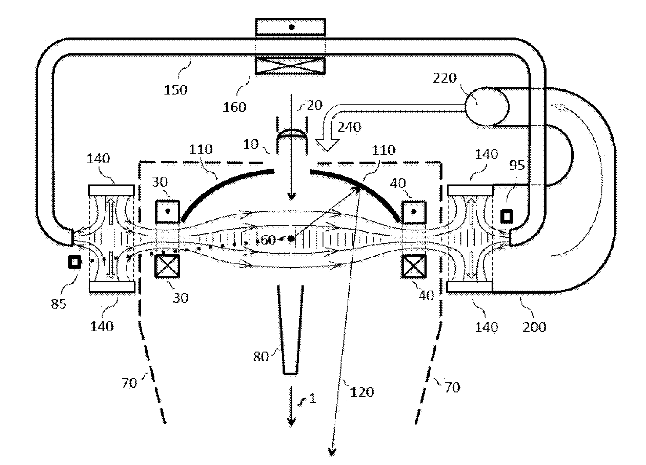
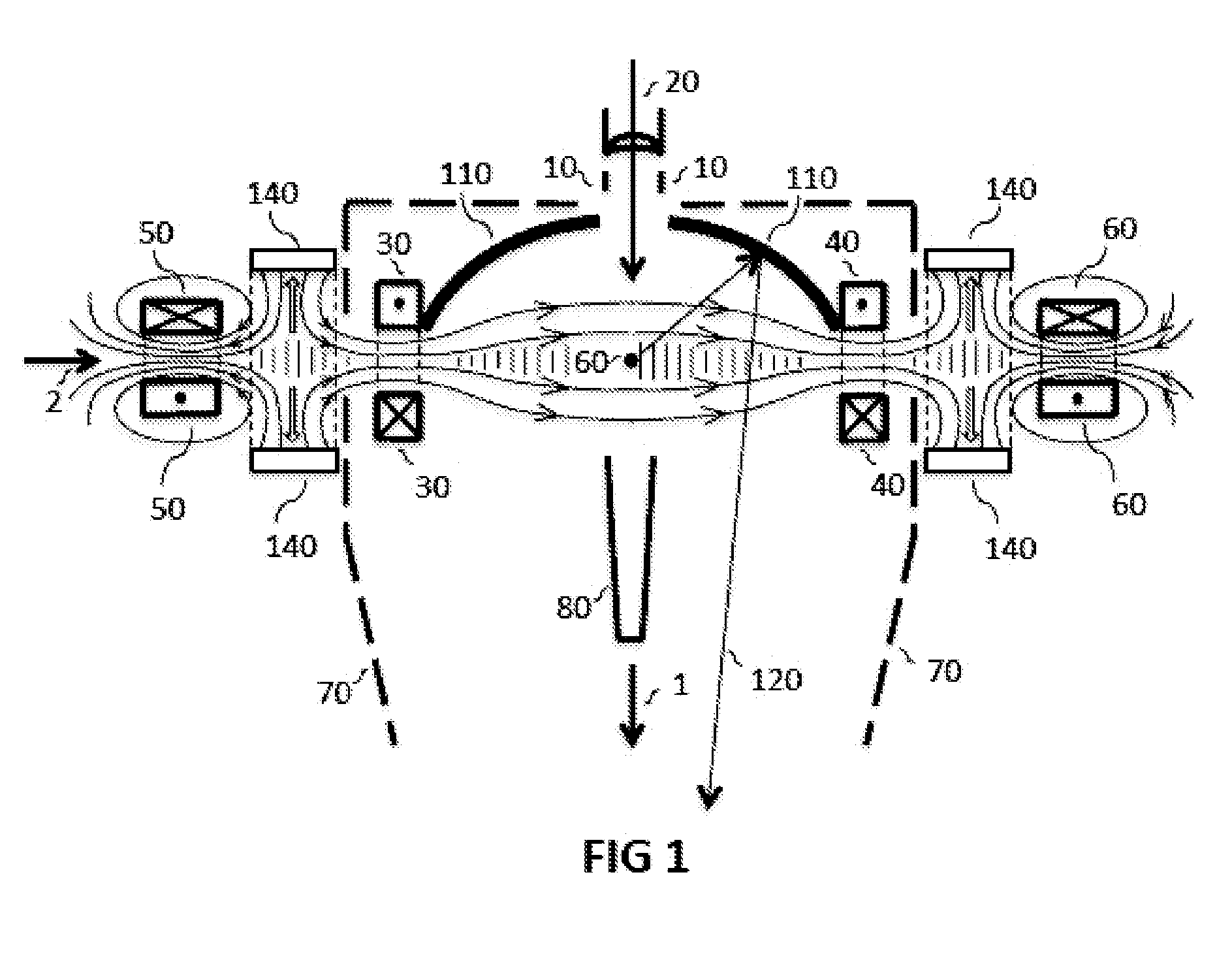
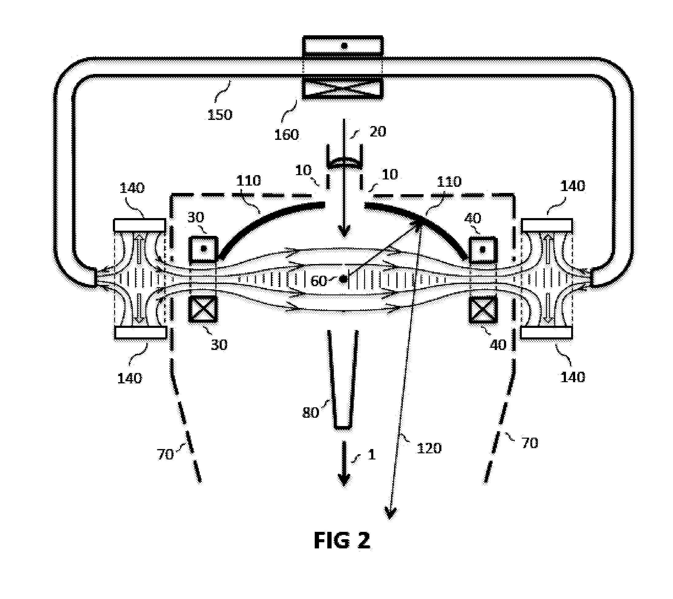
[0021]We describe the magnetic field configuration with reference to FIG. 1. The laser / plasma interaction occurs at central position 60. The laser beams 20 that are necessary to expand and heat incoming droplets may be delivered along the axis of chamber 70, shown as a dashed outline. Chamber 70 has rotational symmetry around symmetry axis 1. For times when droplets are not present, or the target is missed, there is a beam dump 80 for the laser beams. In this drawing the tin droplet stream and catcher for unused droplets are not shown. They may be positioned is several ways, one of which will be shown in FIG. 5. Also symmetrical around axis 1 is the EUV collection mirror 110 which has a central hole to admit the laser beams. A typical ray of EUV light 120 leaves the interaction position 60, reflects off mirror 110 and proceeds to the chamber exit point on axis 1, a position referred to as the “intermediate focus” between the source optic and the stepper illuminator optic. The magnet...


PUM


Abstract

A laser-produced plasma extreme ultraviolet source has a buffer gas to slow ions down and thermalize them in a low-temperature plasma. The plasma is initially trapped in a mirror magnetic field configuration with a low magnetic field barrier to axial motion. Plasma overflows axially at each end of the mirror into magnetic cusps and is conducted by radial magnetic field lines to annular beam dumps disposed around the waist of each cusp.

Description

CROSS REFERENCE TO RELATED APPLICATION[0001]This application claims priority based on Provisional Application Ser. No. 62 / 082,828, filed Nov. 21, 2014, which is hereby incorporated by reference in its entirety.FIELD OF THE INVENTION[0002]This invention relates to the production of extreme ultraviolet (EUV) light especially at 13.5 nm for lithography of semiconductor chips. Specifically it describes configurations of the laser-produced-plasma (LPP) light source type that have improved particle capture and increased plasma heat removal for scaling to ultimate power.BACKGROUND OF THE INVENTION[0003]There is a need for more powerful sources of extreme ultraviolet (EUV) light at 13.5 nm in order to increase the throughput of semiconductor patterning via the process of EUV Lithography. Many different source designs have been proposed and tested (see historical summary for background [1]) including the highly efficient (up to 30%) direct discharge (DPP) lithium approach [2,3,4,5,6,7] and a...

Claims


Application Information

Patent Timeline
Patent Type & Authority Applications(United States)
IPC IPC(8): H05G2/00
CPCH05G2/008H05G2/005
Inventor MCGEOCH, MALCOLM W.
Owner PUREX
Why Eureka
Try Eureka