Method of processing a signal in a hearing instrument, and hearing instrument

a technology of hearing instruments and signals, applied in the field of processing signals in hearing instruments, can solve the problems of time-consuming, difficult to measure, and special equipment, and achieve the effect of simple measurement of sound pressure and measuring impedance in the ear

Active Publication Date: 2014-10-30
SONOVA AG
View PDF1 Cites 60 Cited by
  • Summary
  • Abstract
  • Description
  • Claims
  • Application Information

AI Technical Summary

Benefits of technology

[0029]In accordance with a possibility, in the step of measuring the ear canal impedance, the ear canal impedance is measured by means of a test signal emitted by the receiver and measured by the ear canal microphone. In other embodiments, the ‘normal’ wanted acoustic signal emitted by the receiver is used to measure the impedance. By using the acoustic quantity of the hearing instrument coupled to the standard acoustic coupler this effect can be compensated when calculating the ear canal impedance from the measured signal.
[0030]It is an insight underlying embodiments of the present invention that a simplified impedance measurement that takes into account reference data of the hearing instrument, for example, coupled to a standard coupler, and a simple measurement of the sound pressure by an ear canal microphone can be used to measure the impedance in the ear. The fact that data gained on a single standard coupler can be used as an expedient input for determining the impedance of a real ear canal is surprising. One reason for this is that it has been found that in a hearing instrument, the receiver can be approximated to be an ideal sound flow source, so that the sound flow produced by the receiver becomes approximately independent on the acoustic impedance that it is coupled to. Only due to this insight it becomes possible to use sound signal data recorded from measurements on a single standard volume for determining the real ear canal impedance.

Problems solved by technology

Such a measurement is not straightforward, is time consuming and requires special equipment.
Also, the protruding probe end is prone to being soiled and may cause displeasing sensations to the patient.
Further, the measurement is of limited accurateness because due to the introduction of the probe, additional leakage may be caused through the earpiece.
In addition, there are individual differences because of tubings of different lengths and variations of the earwax protection.
Further, estimations of the corrections are not compatible with the common Real-Ear-to-Coupler Difference (RECD).
While these methods provide some improvement over the prior art in terms of avoiding direct probe contact to the eardrum, they still require a separate probe.
However, an estimation of the sound pressure at the eardrum—and thus also of the RECD—by means of the acoustic reflection or another power quantity is not possible without further input data, especially an estimate of the ear canal cross section.
Most ear canal microphone applications are restricted to controlling the microphone sound pressure and neither comprise calibration nor an estimation of the eardrum sound pressure.
Current models therefore do not appropriately consider the transfer from the ear canal microphone to the eardrum.

Method used


Image

  • Method of processing a signal in a hearing instrument, and hearing instrument
  • Method of processing a signal in a hearing instrument, and hearing instrument
  • Method of processing a signal in a hearing instrument, and hearing instrument

Examples


Embodiment Construction

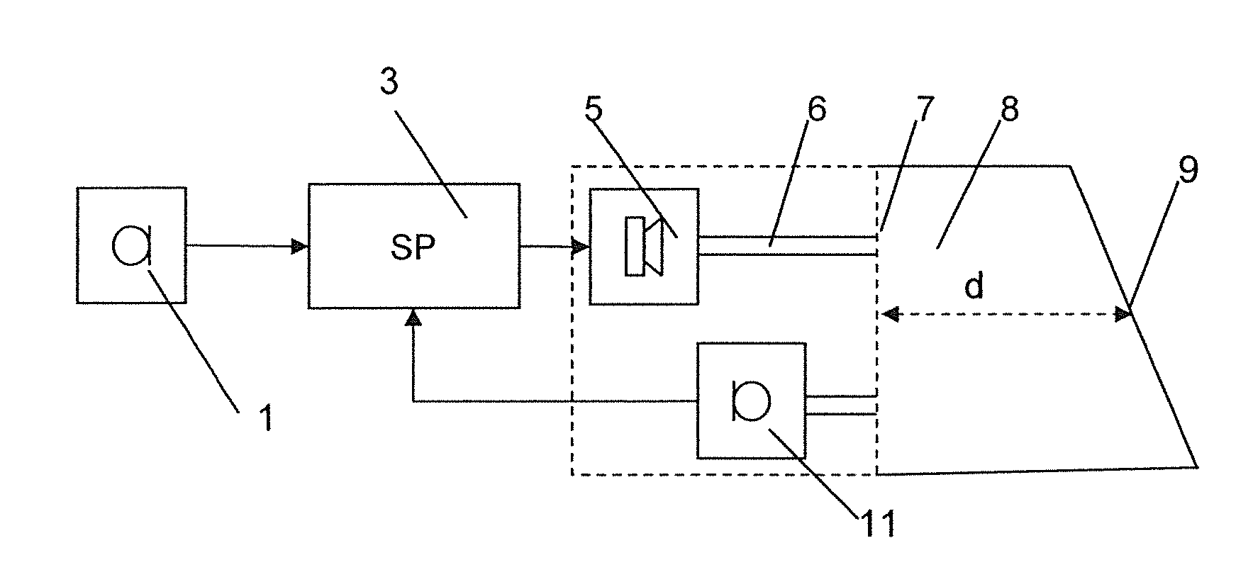
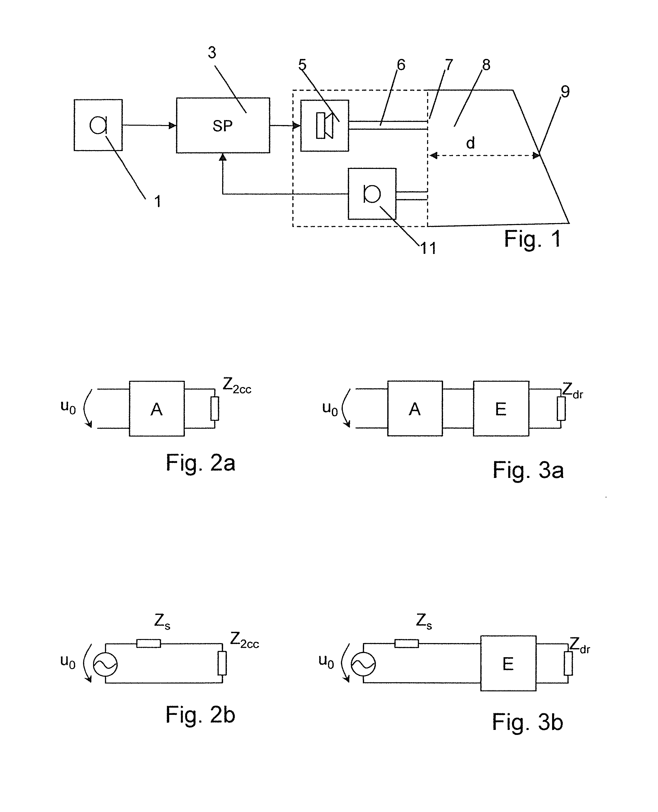
[0074]The hearing instrument schematically represented in FIG. 1 may be of the behind-the-ear (BTE) type, of the in-the-ear (ITE) type, (of the completely-in-the-canal (CIC) type or not) or of any other type. It comprises an input microphone 1. In practice, often more than one input microphones are used, and / or in addition to the input microphone further receiving means for receiving signals may be present, such as a telecoil receiver, a receiving unit including an antenna for receiving wirelessly transmitted signals, etc. The electrical input signal obtained from the at least one input microphone is processed by a signal processing unit 3 to obtain an electrical output signal. The signal processing unit 3 depicted in FIG. 1 may comprise analog-to-digital conversion means and any other auxiliary means in addition to a digital signal processing stage. The signal processing unit may be physically integrated in a single element or may comprise different elements that may optionally be ...


PUM


Abstract

A method of estimating an acoustic transfer quantity representative of a sound pressure transfer to the eardrum includes the steps of measuring, by an ear canal microphone of the hearing instrument, an acoustic signal in the ear canal when a sound signal is emitted into the ear canal by a receiver of the hearing instrument, the ear canal microphone being in acoustic communication with the ear canal, determining, from the acoustic signal and from a frequency dependent reference characteristics of the hearing instrument, an ear canal impedance, and, calculating, from the ear canal impedance, an estimate of the acoustic transfer quantity.

Description

BACKGROUND OF THE INVENTION[0001]1. Field of the Invention[0002]The invention relates to a method of processing a signal in a hearing instrument, and to a hearing instrument, in particular a hearing aid.[0003]2. Description of Related Art[0004]The acoustic coupling of hearing instruments to the tympanic membrane (TM / eardrum) is usually described by means of the Real-Ear-to-Coupler-Difference (RECD) that is indicative of the difference between the sound pressure at the 2 cc coupler (a standardized artificial model of the ear canal) and the sound pressure at the eardrum.[0005]Another quantity that describes the acoustic interplay between the hearing instrument (or that part of the hearing instrument (earpiece) that is inserted into the ear) and the real ear is the Real Ear Occluded Gain (REOG). The REOG describes the sound pressure signal transfer for a sound signal incident on the ear to the eardrum when the hearing instrument is turned off.[0006]According to prior art methods, takin...

Claims


Application Information

Patent Timeline
Patent Type & Authority Applications(United States)
IPC IPC(8): A61B5/12A61B5/00H04R25/00
CPCA61B5/125H04R25/606H04R2225/021H04R2225/023H04R2225/025A61B5/6817H04R25/70H04R2225/0216
Inventor STIRNEMANN, ALFRED
Owner SONOVA AG
Why Eureka
Try Eureka