
Developing roller, developing device, process cartridge, and image forming apparatus

Inactive Publication Date: 2014-10-30
RICOH KK
View PDF5 Cites 13 Cited by
  • Summary
  • Abstract
  • Description
  • Claims
  • Application Information

AI Technical Summary

Benefits of technology

The present invention aims to provide a developing roller that can prevent filming and reduce charges when using toner particles with a core-shell structure and external additives at a high rate. This can solve existing problems and achieve the objective of improving the performance of the developing roller.

Problems solved by technology

As a result, a surface of a developing roller suffers filming of toner particles, which problematically shortens the service life of the developing roller.
As a result, there has been a problem that even a small extent of filming tends to reduce charging.

Method used


Image

  • Developing roller, developing device, process cartridge, and image forming apparatus
  • Developing roller, developing device, process cartridge, and image forming apparatus
  • Developing roller, developing device, process cartridge, and image forming apparatus

Examples


second embodiment

(Developing Roller )

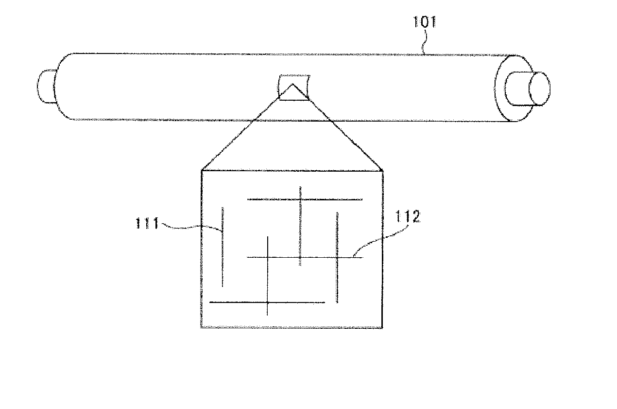
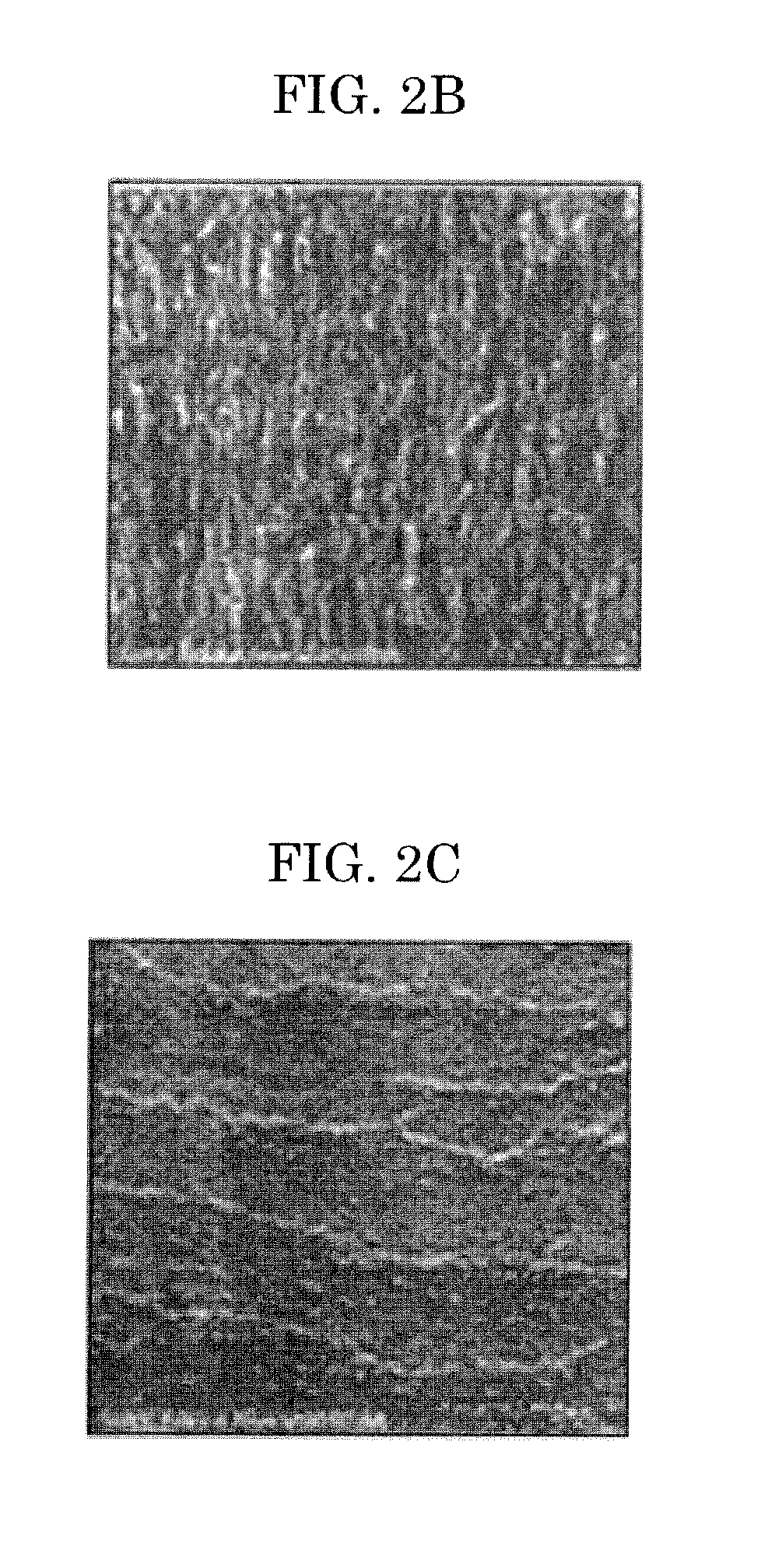
[0042]In the developing roller according to a second embodiment of the present invention, a surface of the surface layer contains a plurality of streaky groove portions each extending along a circumferential direction of the developing roller and a plurality of protruded portions each extending along a direction of the rotational axis of the developing roller. This makes it possible to achieve improvements in, for example, adherence resistance, filming resistance, and stable charging conveyance.

[0043]In a developing device including the developing roller according to the second embodiment, when toner particles having an average circularity of 0.970 or more are used, toner particles in contact with a regulating blade rolls in the concave portions, and replacement of toner particles frequently occurs, whereby charging stability during durable printing can be ensured.

[Surface Structure of the Developing Roller]

[0044]FIGS. 2A to 2C each exemplarily illustrate a surfa...

example 1

[0134]Epichlorohydrin rubber (HYDRIN T3106, product of Zeon Corporation) was extruded onto a metal shaft (SUS) having a diameter of 8 cm so that the rubber had an average thickness of 4 mm, to thereby be formed into a roller. The resultant roller was stored under an environment of 150° C. for 90 min, followed by vulcanizing. Then, a surface of the vulcanized roller was subjected to a coarse polishing by a polishing machine (LEO600-F4L-BME, product of MINAKUCHI MACHINERY WORKS LTD.) until the surface roughness Ra was 1.5 μm and further subjected to a finish polishing by SZC (product of MINAKUCHI MACHINERY WORKS LTD.) using wrapping film #30 under the following conditions: with oscillation, traverse feed velocity: 600 mm / s, tape feed velocity: 25 mm / s, the number of revolutions of the rubber roller: 1,000 rpm, and 1 pass-polishing, to thereby obtain a rubber substrate for a developing roller (a substrate in which an elastic layer is provided on a circumference of a metal shaft).

[0135]...

example 2

[0137]A developing roller of Example 2 was obtained in the same manner as in Example 1, except that the silica was changed to hydrophobic silica R976S (product of Nippon Aerosil Co., Ltd., average primary particle diameter: 5 nm to 7 nm), and the fluoroethylene vinyl ether copolymer was changed to 0.0290 parts of a fluoroethylene vinyl ether copolymer (LF916, product of ASAHI GLASS CO., LTD.).


PUM


Abstract

A developing roller, including: a shaft containing a metal; an elastic layer on a circumference of the shaft; and a surface layer on a circumferential surface of the elastic layer, wherein the surface layer contains: a polyurethane which is a reaction product between a fluoroethylene vinyl ether copolymer and an isocyanurate form of an isocyanate; and particles having an average primary particle diameter of 5 nm to 30 nm, and wherein the polyurethane has a peak intensity ratio of a NCO group to a hydroxyl group of 5.6 to 8.8 in an infrared absorption spectrum obtained by an attenuated total reflection method.

Description

BACKGROUND OF THE INVENTION[0001]1. Field of the Invention[0002]The present invention relates to a developing roller, a developing device, a process cartridge, and an image forming apparatus.[0003]2. Description of the Related Art[0004]One-component development is known as a small-sized, inexpensive developing system. In this one-component development, however, it is necessary to apply high linear pressure to toner particles using a regulating blade for stabilizing charging conveyance. As a result, a surface of a developing roller suffers filming of toner particles, which problematically shortens the service life of the developing roller. In order to solve this problem, there has been proposed a technique of preventing filming by improving releaseability of a surface layer of the developing roller.[0005]For example, for the purpose of providing an electroconductive roller which can provide a clear image even under severe printing conditions in a HH environment and which is especiall...

Claims


Application Information

Patent Timeline
IPC IPC(8): G03G15/08
CPCG03G15/0812G03G21/18G03G15/0865G03G15/0818
Inventor YASUNAGA, HIDEAKIJURI, KEIICHIROTAKEUCHI, YUTANOZAKI, TSUYOSHIISHIKAWA, YOSHIMICHIMIKI, TOMOHARU
Owner RICOH KK
Learn More