Method and production facility for manufacturing a wind turbine blade

a manufacturing method and technology for wind turbine blades, applied in the field of manufacturing methods can solve the problems of increasing production costs and rendering the manufacture of wind turbine blades increasingly difficul

Active Publication Date: 2014-10-30
VESTAS WIND SYST AS
View PDF2 Cites 33 Cited by
  • Summary
  • Abstract
  • Description
  • Claims
  • Application Information

AI Technical Summary

Benefits of technology

[0006]The above objects, together with numerous other objects, advantages, and features, which will become evident from the below description, are accomplished by a solution in accordance with the present invention by a method for manufacturing a wind turbine blade in a production facility, comprising the steps of
[0012]Hereby, a flexible manufacturing method is provided, wherein a gantry may be moved from a first mould part to a second mould part (or vice versa) so that more gantries and thereby tools may be allocated to a specific mould part, which seen from a manufacturing point of view is desirable with a view to increasing the speed in some of the manufacturing steps. Furthermore, since the gantries are moveable between different mould parts, it is also possible to have fewer gantries, thus making investment related to the production facility less burdensome.

Problems solved by technology

This poses challenges in the manufacturing of the blades, as moulds, handling units and tools are also to be enhanced in size, which is adding to the production costs as well as rendering the manufacture of wind turbine blades increasingly difficult.

Method used


Image

  • Method and production facility for manufacturing a wind turbine blade
  • Method and production facility for manufacturing a wind turbine blade
  • Method and production facility for manufacturing a wind turbine blade

Examples


Embodiment Construction

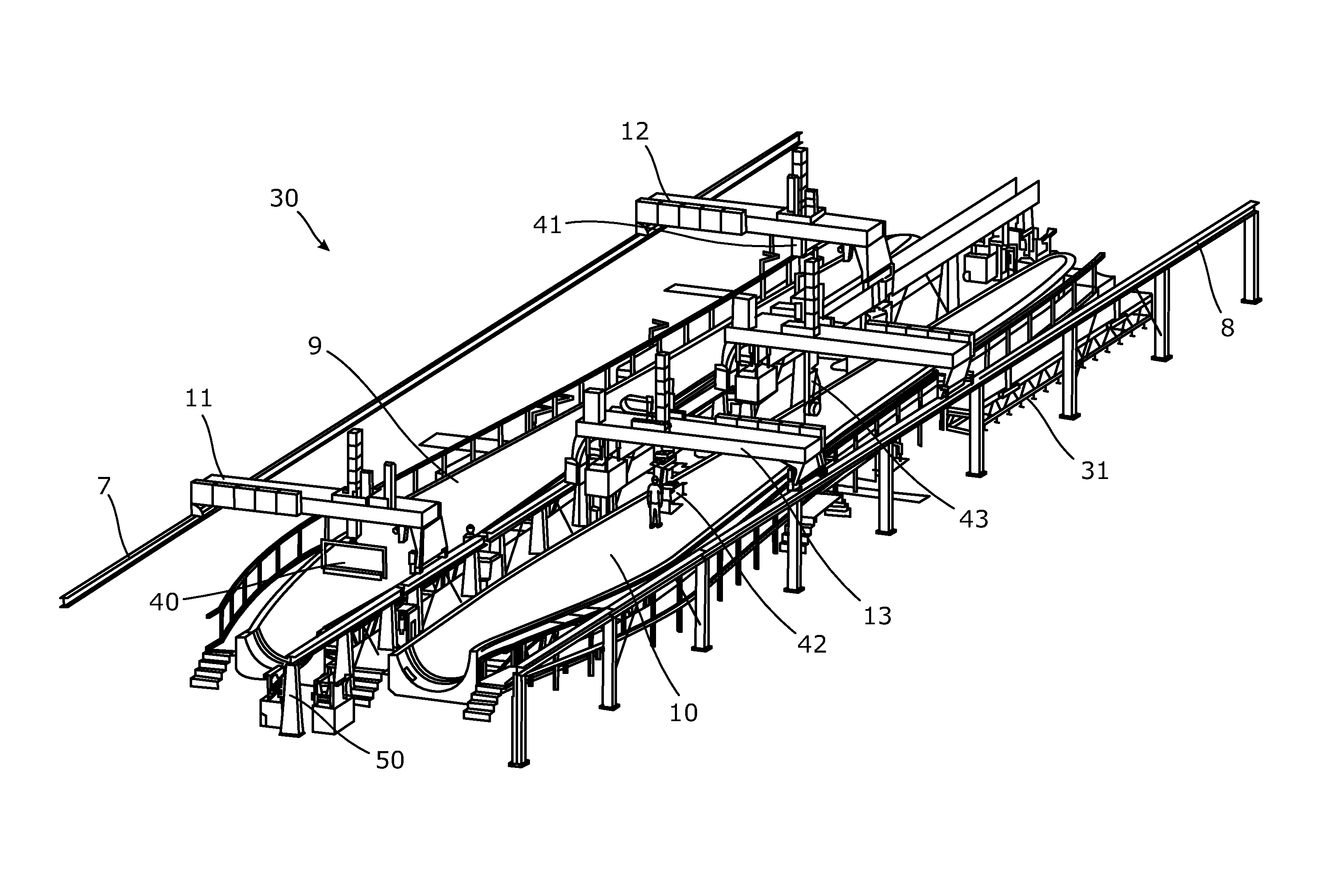
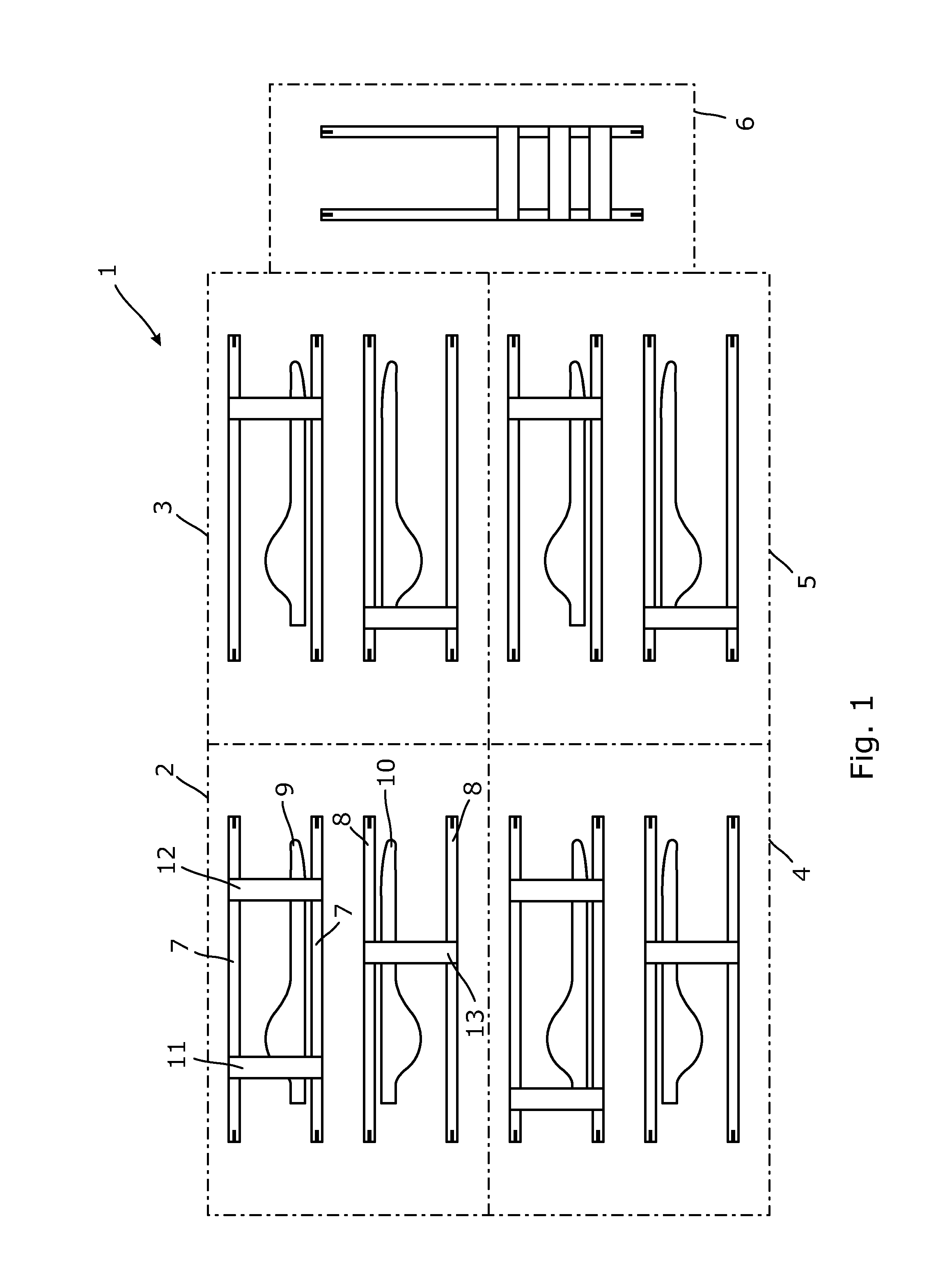
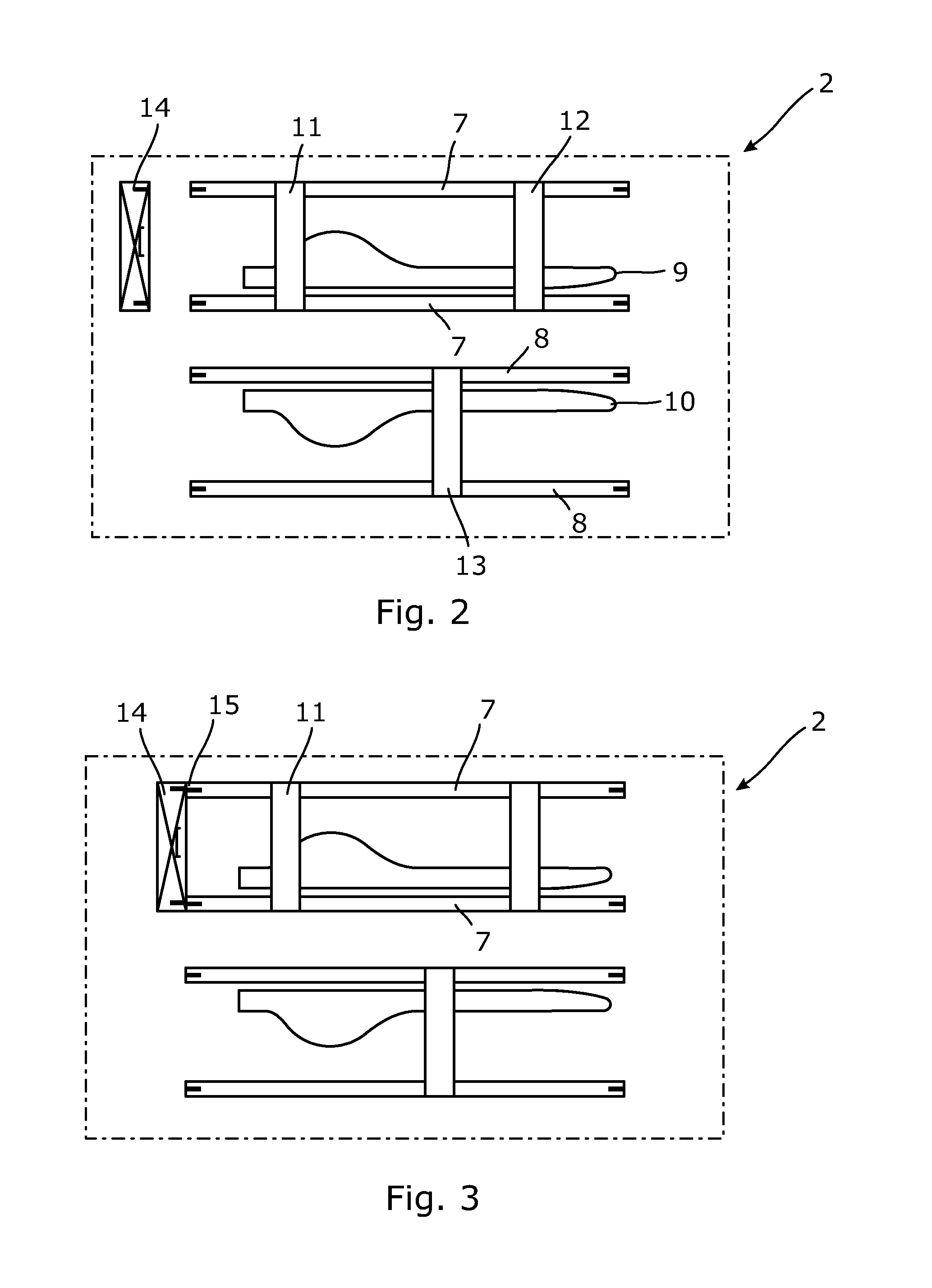
[0054]In FIG. 1 a production facility 1 for manufacturing wind turbine blades is shown schematically in a top view. The production facility 1 comprises five working stations 2-6. The working stations 2-5 each comprises a first pair of rails 7 and a second pair of rails. For the sake of clarity, in the following only working station 2 will be described. However, the other working stations 3-5 may comprise the same elements as working station 2 even though they have not been indicated in the figures.

[0055]In working station 2, the first pair of rails 7 extends along an elongated first mould part 9 for manufacturing one of a first part and a second part of the blade (not shown). The second pair of rails 8 extends along an elongated second mould part 10 for manufacturing the other of the first and the second part of the blade (not shown).

[0056]A first overhung gantry 11 and a second overhung gantry 12 are extending transversely over the first mould part 9. A third overhung gantry 13 ext...


PUM

PropertyMeasurementUnit
sizeaaaaaaaaaa
lengthaaaaaaaaaa
flexibleaaaaaaaaaa

Abstract

The present invention relates to a method for manufacturing a wind turbine blade in a production facility. The method comprises the steps of positioning a first overhung gantry to extend transversely over an elongated first mould part for manufacturing one of a first part and a second part of the blade, performing a first working action at the first mould part with a first tool mounted on the first overhung gantry, moving the first overhung gantry from the first mould part to an elongated second mould part for manufacturing the other of the first and the second part of the blade, positioning the first overhung gantry to extend transversely over the second mould part, and performing a second working action at the second mould part by means of the first tool or a second tool mounted on the first overhung gantry.

Description

FIELD OF THE INVENTION[0001]The present invention relates to a method for manufacturing a wind turbine blade in a production facility. Furthermore, the invention relates to a production facility for manufacturing a wind turbine blade, and finally the invention relates to a wind turbine blade manufactured according to the method according to the present invention.BACKGROUND ART[0002]Wind turbines are increasing in size, causing their wind turbine blades to increase in size as well, both with respect to length and chord.[0003]This poses challenges in the manufacturing of the blades, as moulds, handling units and tools are also to be enhanced in size, which is adding to the production costs as well as rendering the manufacture of wind turbine blades increasingly difficult.[0004]Therefore, it is desirable to provide a flexible way of manufacturing wind turbine blades.SUMMARY OF THE INVENTION[0005]It is an object of the present invention to wholly or partly overcome the above disadvantag...

Claims


Application Information

Patent Timeline
Patent Type & Authority Applications(United States)
IPC IPC(8): B23P15/04F03D1/06
CPCF03D1/0675B23P15/04B29C70/38B29D99/0028Y10T29/53961Y10T29/49337Y02E10/72
Inventor TAPIA, RAUL GARCIA
Owner VESTAS WIND SYST AS
Why Eureka
Try Eureka