Fluid-pressure apparatus

a technology of fluid pressure apparatus and fluid pressure, which is applied in the direction of liquid fuel engines, machines/engines, rotary/oscillating piston pump components, etc., can solve the problems of operation noise and damage to the fluid pressure apparatus, and achieve high output efficiency, prevent the damage of the edges, and prevent the leakage of the operation fluid

Active Publication Date: 2014-10-30
SUMITOMO PRECISION PROD CO LTD
View PDF2 Cites 4 Cited by
  • Summary
  • Abstract
  • Description
  • Claims
  • Application Information

AI Technical Summary

Benefits of technology

[0045]As described in detail above, according to the fluid-pressure apparatus of the present invention, since, on the edges of the end surfaces of the tooth portions of the gears, at least the intermediate parts between the tooth tips and the tooth bottoms are chamfered and the roundness or inclination of the intermediate parts is made larger than those of the tooth tips and the tooth bottoms, it is possible to prevent the edges from being damaged due to contact force generated when the pair of gears mesh with each other, and it is possible to prevent leakage of the operation fluid through between the gears and the support members. Thereby, the original performance of being quiet and having high output efficiency can be maintained for a long time and higher reliability than before can be obtained.

Problems solved by technology

Such fluid-pressure apparatuses have a problem of operational noise generated by meshing of gears, a problem of noise generated by discontinuous change of the volume of the liquid confined between tooth surfaces of the meshing gears, and the like.

Method used


Image

  • Fluid-pressure apparatus
  • Fluid-pressure apparatus
  • Fluid-pressure apparatus

Examples


example

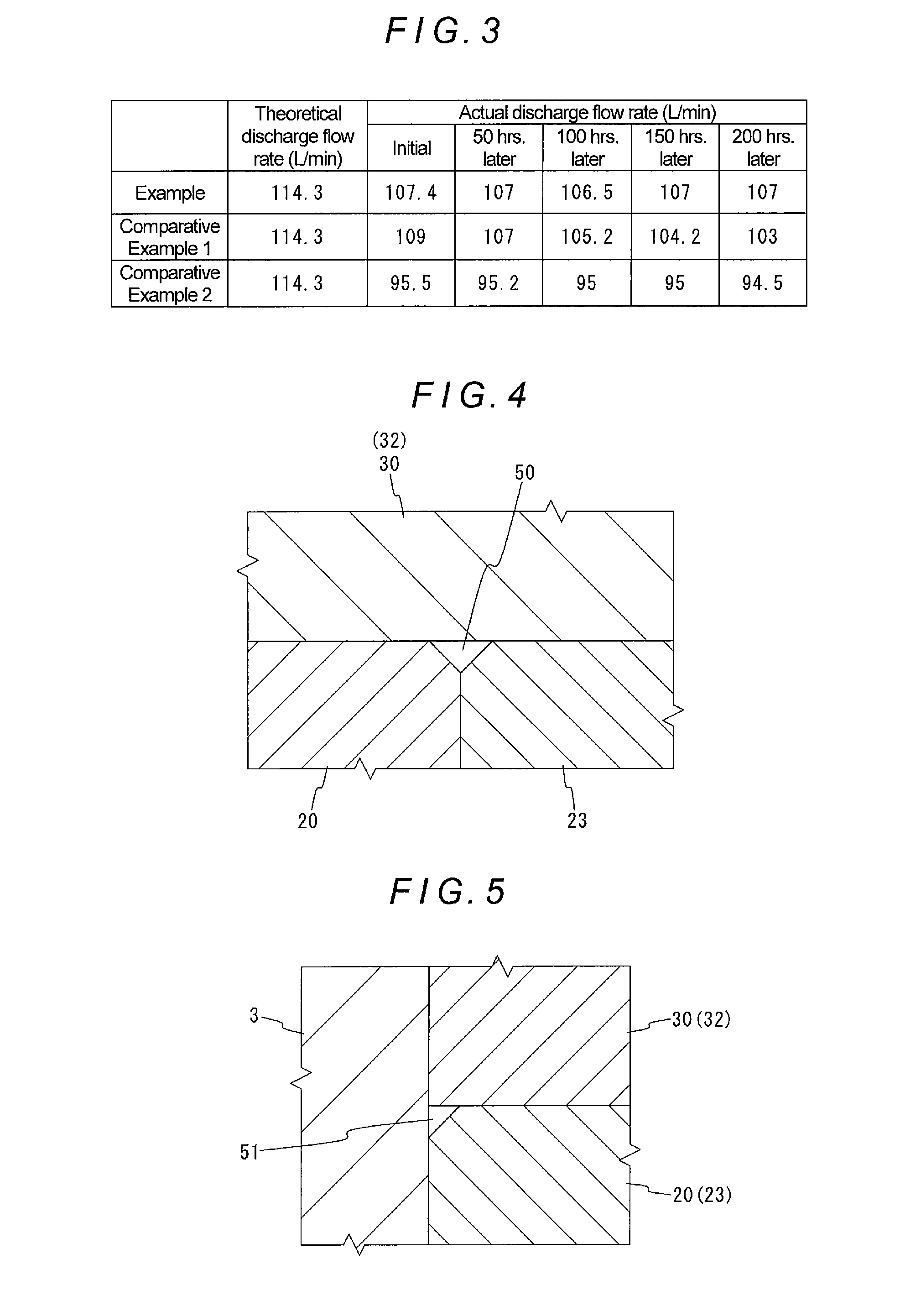
[0074]In this connection, the inventor of the present application performed a performance comparison experiment using an oil hydraulic pump corresponding to the conventional oil hydraulic device 1 using helical gears the edges of the tooth portions of which are not chamfered (Comparative Example 1), an oil hydraulic pump using helical gears the entire edges of the tooth portions of which are chamfered (Comparative Example 2) and an oil hydraulic pump using helical gears only the acute-angle edge portions of the tooth portions of which are chamfered so that the width of chamfering of the intermediate part between tooth tip part and the tooth bottom part is larger than those of the tooth tip part and the tooth bottom part (Example). The results thereof are described below. It is noted that FIG. 3 is a table which indicates the results obtained when the above-mentioned oil hydraulic pumps were driven and the discharge flow rates thereof were measured at a predetermined time interval.

[0...


PUM


Abstract

A pair of meshed gears is disposed in a hydraulic chamber of a housing. Bushes in the chamber contact both end surfaces of the gears. Edge surfaces of the gears are chamfered at intermediate parts between tooth tips and tooth bottoms, and the inclination of the intermediate parts is larger than those of the tooth tips and bottom, thereby protecting the edges from damage due to contact force as the gears mesh and preventing leakage between the gears and the support members. Accordingly, the gears may be operated quietly, at high output efficiency, and increased reliability for an extended period.

Description

TECHNICAL FIELD[0001]The present invention relates to a fluid-pressure apparatus having a pair of gears whose tooth surfaces mesh with each other.BACKGROUND ART[0002]As a fluid-pressure apparatus as mentioned above, a hydraulic pump which rotates a pair of gears by an appropriate drive motor and pressurizes an operation fluid by the rotational motions of the gears and discharges the pressurized operation fluid, and a hydraulic motor which rotates gears by introducing a previously pressurized operation fluid therein and uses rotational forces of rotating shafts of the gears as a power are conventionally known.[0003]Such fluid-pressure apparatuses have a problem of operational noise generated by meshing of gears, a problem of noise generated by discontinuous change of the volume of the liquid confined between tooth surfaces of the meshing gears, and the like. In order to reduced such noise, conventionally a fluid-pressure apparatus using a pair of gears having a theoretical tooth prof...

Claims


Application Information

Patent Timeline
Patent Type & Authority Applications(United States)
IPC IPC(8): F04C2/18F01C1/18
CPCF01C1/18F04C2/18F04C2270/13F04C2/084F03C2/08F04C14/28F04C15/0049F01C1/084F04C2/16F01C1/16F04C18/18F04C18/16F04C18/084
Inventor TAKEDA, HIROAKI
Owner SUMITOMO PRECISION PROD CO LTD
Why Eureka
Try Eureka