Apparatus for subcutaneous electrode insertion

a technology of electrodes and apparatus, applied in the field of medical treatments, can solve problems such as perforation, fracture after repeated stress, and many problems, and achieve the effects of reducing the risk of fracture, and improving the safety of patients

Inactive Publication Date: 2014-10-30
CAMERON HEALTH
View PDF3 Cites 7 Cited by
  • Summary
  • Abstract
  • Description
  • Claims
  • Application Information

AI Technical Summary

Benefits of technology

[0012]In yet a further embodiment, the insertion tool, at least during the second insertion through the first incision, is inserted with a sheath placed thereover. Once the insertion tool and sheath are inserted to a desired extent, the insertion tool is removed, leaving the sheath in place. Then the electrode / lead assembly is inserted into the sheath to a desired extent. Finally, the sheath is removed. Preferably the sheath includes a line of axial weakness, or is a splittable sheath, so that it can be removed over the electrode / lead assembly without damaging or moving the assembly.

Problems solved by technology

Several difficulties with such treatments relate to placement and durability of electrodes.
Once placed, leads may fracture after being subjected to repeated stresses as the heart beats and the patient moves.
Because implantation requires traversing the vasculature as well as placement and anchoring within the heart, many problems can arise.
Pushing the lead stresses the lead and can cause lead failure.
While extra stiffness may help with lead insertion and aid accurate lead placement, stiffer leads create their own problems with migration, perforation, and fracture.
Further, with extra stiffness, the lead does not rest in place during muscle movement, tending to increase the size of any associated fibroid, and potentially leading to migration.

Method used


Image

  • Apparatus for subcutaneous electrode insertion
  • Apparatus for subcutaneous electrode insertion
  • Apparatus for subcutaneous electrode insertion

Examples


Embodiment Construction

[0025]The following detailed description should be read with reference to the drawings. The drawings, which are not necessarily to scale, depict illustrative embodiments and are not intended to limit the scope of the invention.

[0026]It should be noted that the terms “lead” and “lead electrode assembly” as used herein carry distinct meanings, with a lead electrode assembly being a lead and electrode coupled together. U.S. patent application Ser. No. 09 / 940,377 to Bardy et al., now U.S. Pat. No. 6,866,044, is incorporated herein by reference. Bardy et al. suggest several methods for insertion of a defibrillator device including a subcutaneous canister and electrode(s), and explain additional details of subcutaneous defibrillation devices and methods.

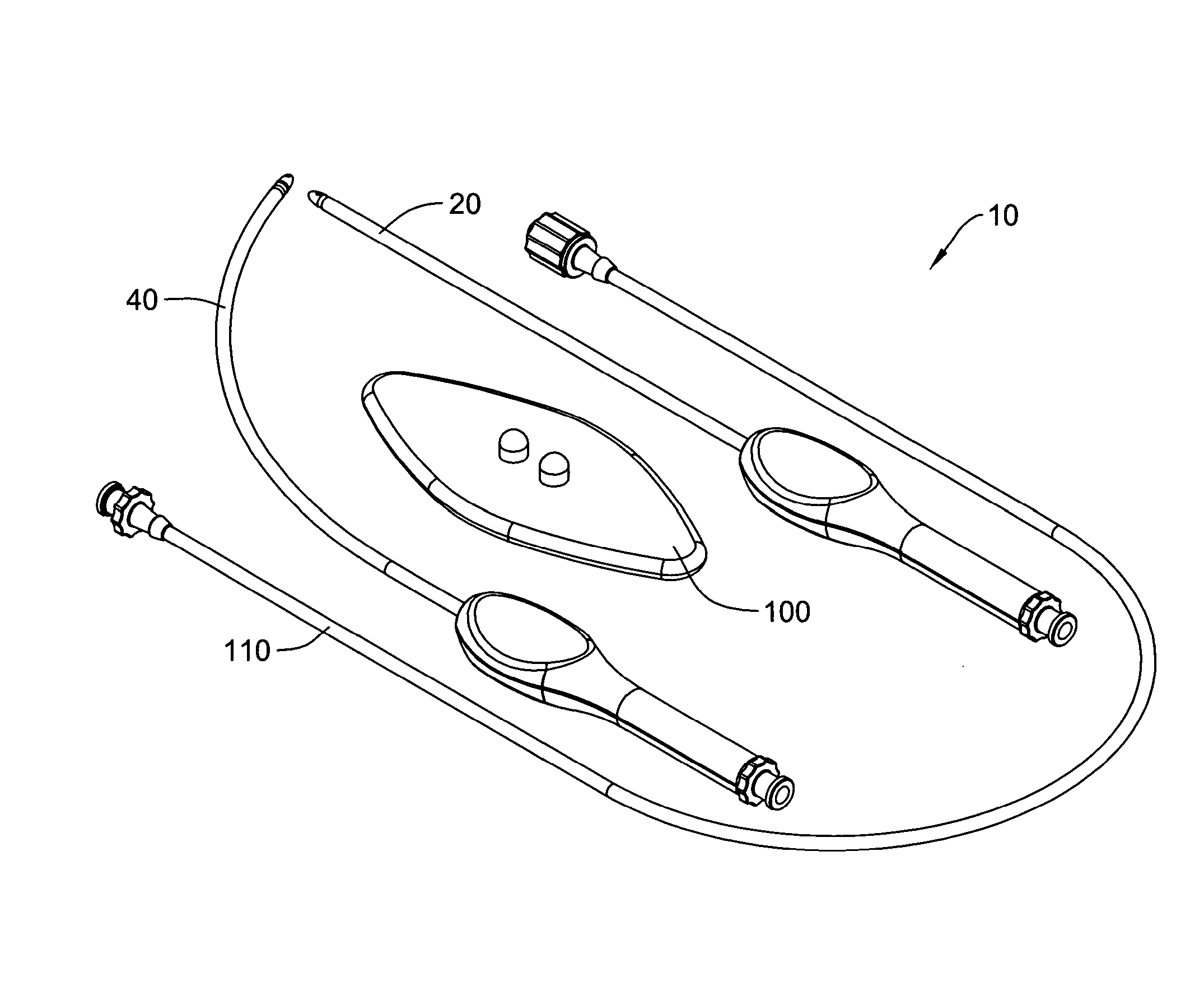
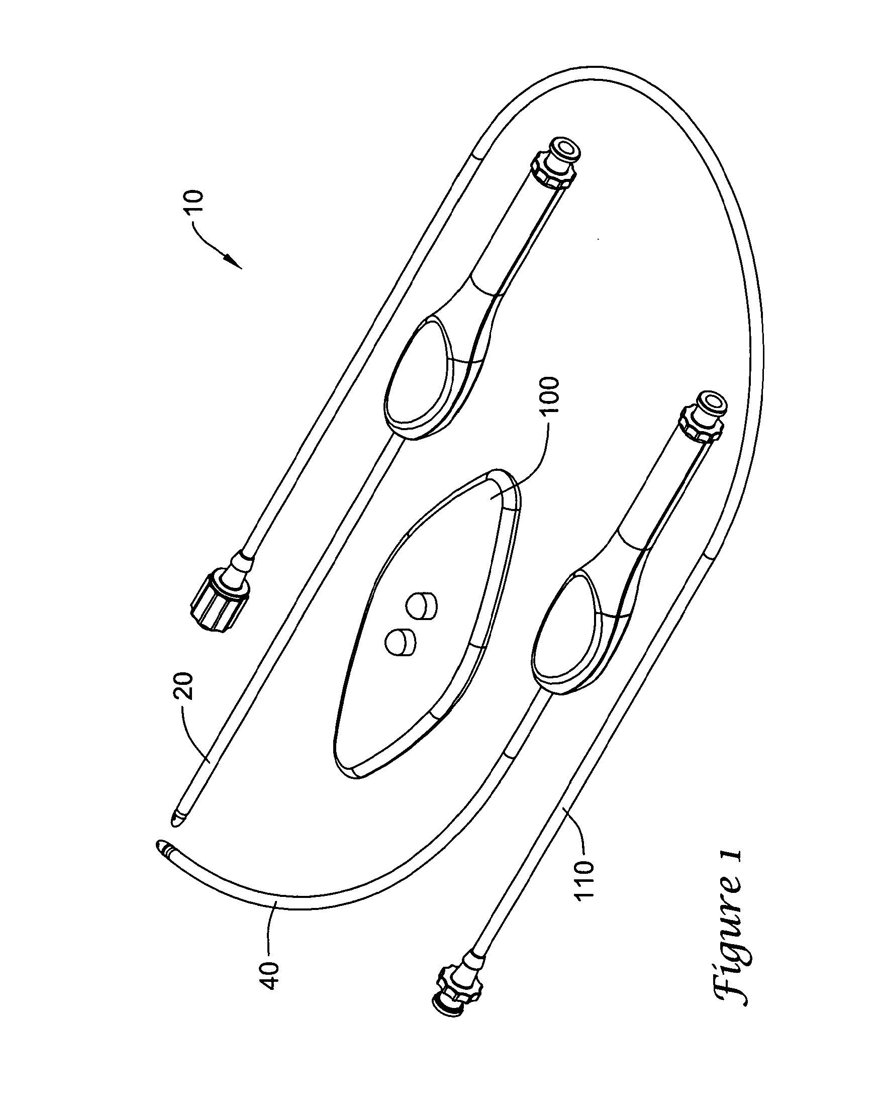
[0027]FIG. 1 illustrates in perspective view a lead electrode assembly insertion tool kit including several components. The kit 10 includes a number of items, including a straight insertion tool 20, a curved insertion tool 40, a bending to...


PUM


Abstract

Devices and methods for electrode implantation. A first embodiment includes an electrode insertion tool adapted to tunnel through tissue and attach, at its distal end, to a lead, such that the lead may be pulled into the tunneled space as the electrode insertion tool is removed. Additional embodiments include methods for inserting electrode/lead assemblies, including a method wherein an insertion tool is first used to tunnel through tissue, then to pull an electrode/lead into the tunneled space. In a further embodiment the insertion tool is next used, with a splittable sheath disposed thereon, to create an additional path into tissue, after which the insertion tool is removed, leaving the sheath in place; a lead is inserted to the sheath, and, finally, the splittable sheath is removed over the lead.

Description

RELATED APPLICATIONS[0001]This application is a continuation of U.S. patent application Ser. No. 13 / 436,438, filed Mar. 30, 2012, published as US 2012-0191106 A1, which is a continuation of U.S. patent application Ser. No. 12 / 698,627, filed Feb. 2, 2010, published as US 2010-0137879 A1, and titled APPARATUS AND METHOD FOR SUBCUTANEOUS ELECTRODE INSERTION, now issued as U.S. Pat. No. 8,157,813, which is a continuation of U.S. patent application Ser. No. 11 / 006,291, filed Dec. 6, 2004, now U.S. Pat. No. 7,655,014 and titled APPARATUS AND METHOD FOR SUBCUTANEOUS ELECTRODE INSERTION, the entire disclosure of which is incorporated herein by reference.FIELD[0002]The present invention is related to the field of medical treatments including electrode implantations. More particularly, the present invention is related to the field of electrode implantation or insertion for cardiac treatments.BACKGROUND[0003]The use of implantable pacing and defibrillation devices to treat or prevent various c...

Claims


Application Information

Patent Timeline
Patent Type & Authority Applications(United States)
IPC IPC(8): A61N1/05
CPCA61N1/05A61M25/0668A61N1/056
Inventor KO, MICHAELTUMLINSON, DUANE
Owner CAMERON HEALTH
Why Eureka
Try Eureka