Electrokinetic micro power cell using pile-up disk type microfluidic-chip with multi-channel

a microfluidic chip and micro-power cell technology, applied in the field of micro-power cells, can solve the problems of not developing a power cell capable of commercializing streaming potential, and achieve the effect of increasing the number of microchannels

Inactive Publication Date: 2010-05-04
KOREA INST OF SCI & TECH
View PDF2 Cites 5 Cited by
  • Summary
  • Abstract
  • Description
  • Claims
  • Application Information

AI Technical Summary

Benefits of technology

[0029]An electrokinetic micro power cell according to the invention is able to achieve the uniform flows into all individual microchannels of the disk type chip, thereby obtaining a stable energy. As the number of the channels is increased due to the pile-up of the chips, the external current is increased so that a more increased electric energy can be obtained.
[0030]Accordingly, the object of the present invention is to provide a micro power cell using a pile-up disk type microfluidic-chip with multi microchannels capable of generating a more increased electric energy.
[0045]According to an embodiment of the invention, in order to protect the pile-up chip and to prevent a water leakage, plastic rings are preferably provided between the chip and the connection part and between the chip and the chip insertion part.
[0049]It is possible to vertically bond the disk type microfluidic-chips with the RIE apparatus, thereby fabricating a pile-up disk type microfluidic-chip having highly increased the number of microchannels.

Problems solved by technology

Until now, however, it has not been developed a power cell capable of commercializing the streaming potential.

Method used


Image

  • Electrokinetic micro power cell using pile-up disk type microfluidic-chip with multi-channel
  • Electrokinetic micro power cell using pile-up disk type microfluidic-chip with multi-channel
  • Electrokinetic micro power cell using pile-up disk type microfluidic-chip with multi-channel

Examples


example 1

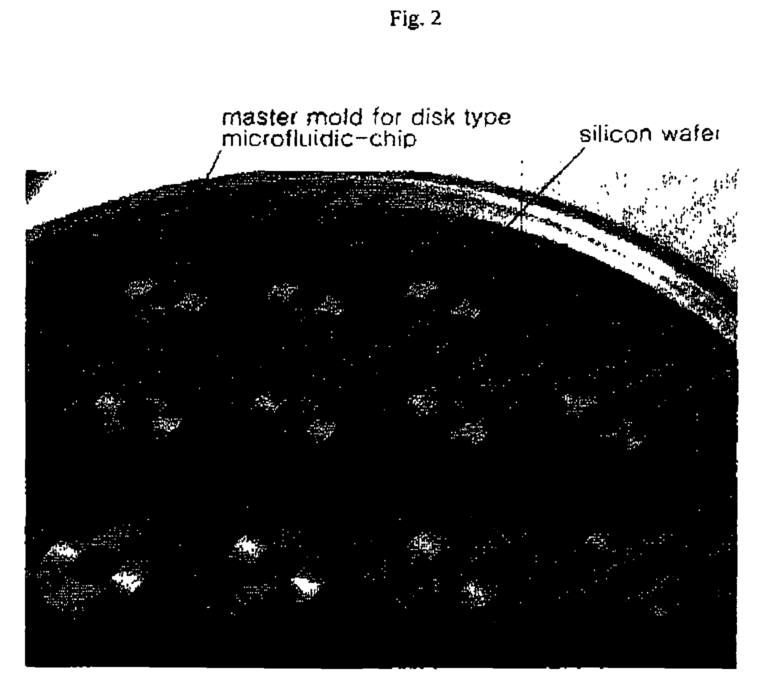
Fabricating a Disk Type Microfluidic-chip with a Multi Microchannel and Piling Up

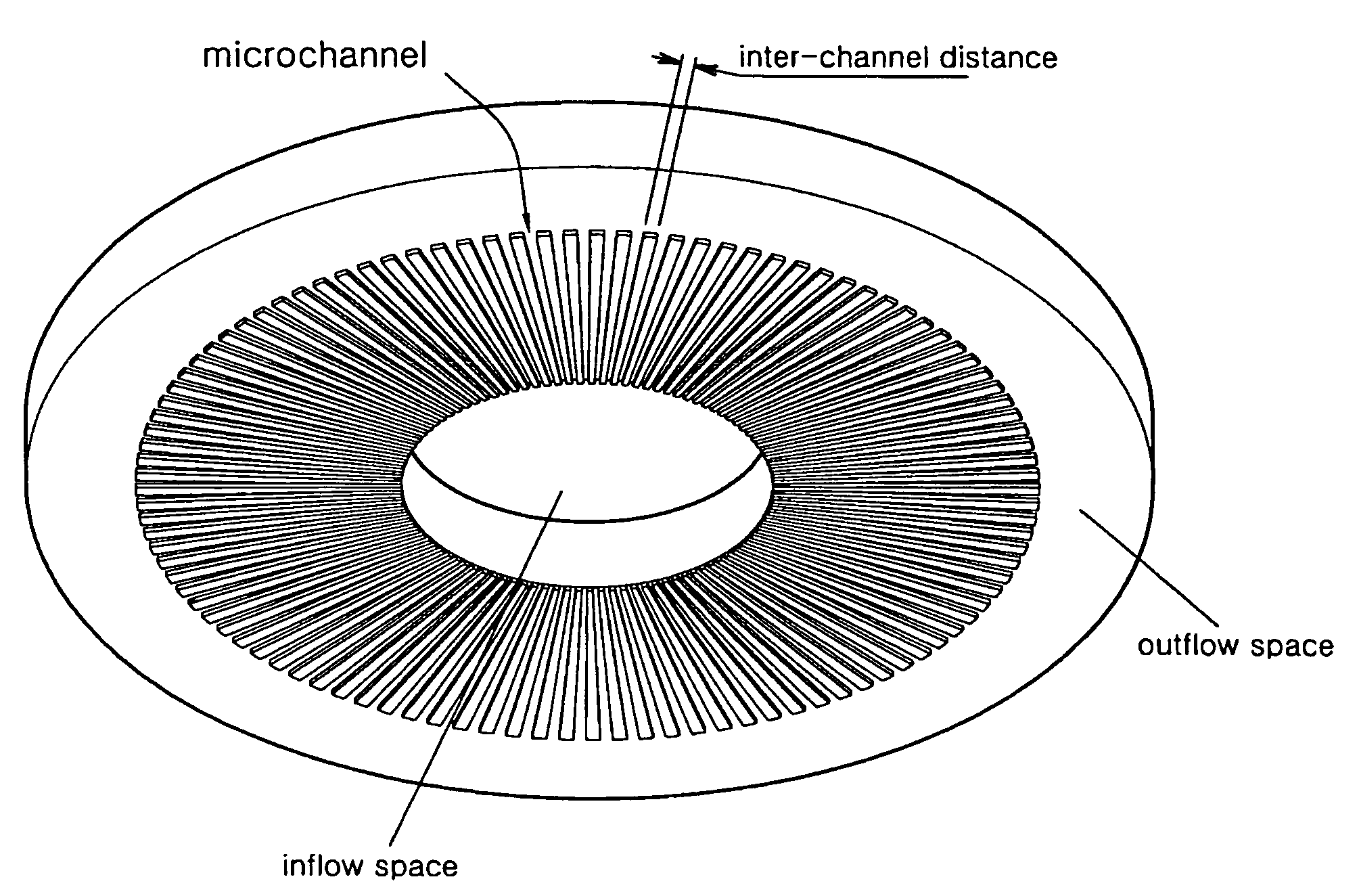
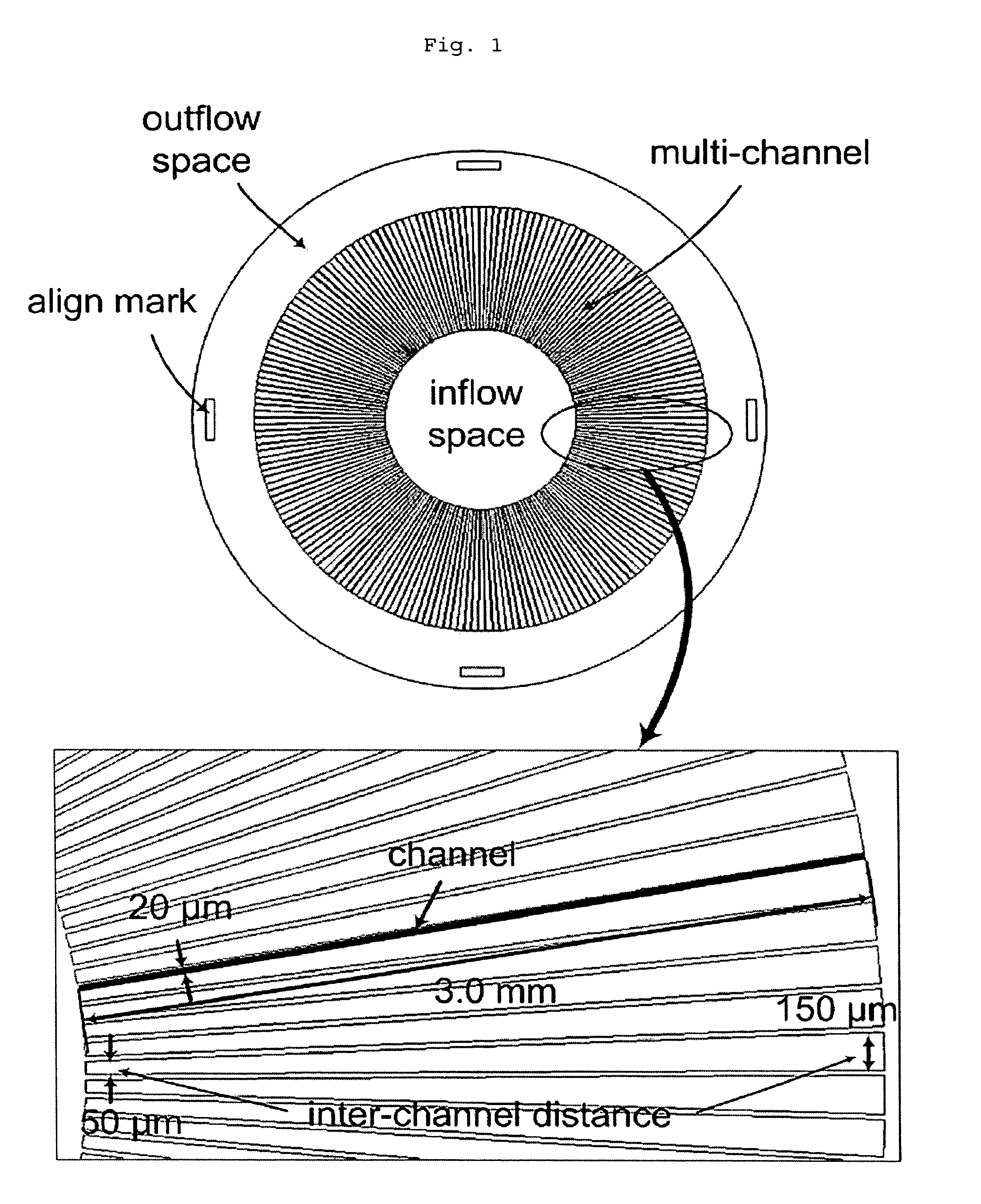
[0065]FIG. 1 is showing a photomask designed with AutoCad® 2004, which is a first step for fabricating a microfluidic-chip according to the invention. The photomask for the chip fabricating comprises an inflow space of a fluid, a multi microchannel, an alignment mark and an outflow space.

[0066]The inflow space through which the fluid flows in the chip is designed in consideration for a diameter of an electrode because an Ag / AgCl electrode having a diameter of 2 mm should be located therein. About 200 microchannels are arranged in a fan-bracings shape around the inflow space at a regular interval. Owing to such design, when the fluid flows in the 200 microchannels, the fluid can flow in each inlet of the microchannels and equivalently flow out of an outlet of the microchannel. If the microchannels are not arranged at a regular interval, the fluid flow deviates from this behavior, so that a potential diff...

example 2

Fabricating of a Streaming Potential Cell Having a Pile-up Chip Mounted in a Holder

[0074]FIG. 5 is a design view of a holder containing a pile-up disk type microfluidic-chip 1 therein according to an embodiment of the invention. The chip containing holder made of semi-transparent acrylic resin comprises a fluid flow-in 7, a distributor 5, a chip insertion part 4, a collector 6, a connection part 2, a cover part 3, a flow-out 8, Ag / AgCl electrodes 9, 10 and an electrode insertion part.

[0075]The flow-in 7 and the flow-out 8 have a diameter determined so as to be connected to external tubing. According to this embodiment, the diameter is designed to be 7 mm so as to be connected to tubing having an outer diameter of ⅛ inch. The flow-in 7 is positioned to be below the flow-out 8 on the basis of a gravity direction so that the fluid can faithfully flow into the multi microchannel of the pile-up microfluidic-chip by the pressure difference.

[0076]Since the Ag / AgCl electrodes are inserted i...

example 3

An Experiment of Measuring a Streaming Potential of a Micro Power Cell According to the Invention and an External Current

[0083]An electrokinetic micro power cell as shown in FIG. 8 was developed using the streaming potential cell prepared according to the above embodiment. The fluid is supplied to the flow-in 7 of the holder using a syringe pump (Cole-Parmer 74900 Series, IL) 11, passes through the microchannels of the pile-up disk type microfluidic-chip 1 and then is discharged to the flow-out 8. At this time, a pressure difference Δp between both ends of the microchannel was measured with a precision pressure gauge 15 and a streaming potential difference ΔE between both ends of the microchannel was measured with a high-precision digital multi-meter (HP34970A, Hewlett-Packard Co., CA) 13 through the Ag / AgCl electrodes 9, 10 arranged to upper and lower parts of the holder.

[0084]FIG. 9 depicts the results showing measurements of a streaming potential in accordance with a pressure dif...


PUM

PropertyMeasurementUnit
lengthaaaaaaaaaa
lengthaaaaaaaaaa
depthaaaaaaaaaa

Abstract

Disclosed is a micro power cell capable of being applied as an energy source and utilizing a streaming potential phenomenon occurring in accordance with an electrokinetic principle when an electrolyte aqueous solution flows in the microchannels piled up in several layers. The streaming potential cell consists of a PDMS microfluidic-chip fabricated by MEMS process as well as micromachining technology. The microfluidic-chip is formed with multi microchannels radially arranged in parallel with each other around a center of a disk at a regular interval. The disk type multi microchannel can achieve uniform inflow and outflow effects. According to the invention, there is provided a cell device comprising a pile-up chip having a number of disk type microfluidic-chips with the optimal structure of flow-in and flow-out of a fluid, a distributor, a collector, an electrode insertion part, etc.

Description

BACKGROUND OF THE INVENTION[0001]1. Field of the Invention[0002]The present invention relates to a micro power cell capable of piling up a disk type microfluidic-chip to generate an electric energy by a streaming potential of a fluid flowing through a multi micro channel of the chip.[0003]2. Description of the Prior Art[0004]When fluid flows through a charged channel by pressure gradient, the density of counter-ions whose charge is opposite to that of the wall surface becomes higher near the surface of the channel wall, resulting in an establishment of the electric double layer (so-called Debye layer). Counter-ions in the electric double layer generate the streaming current by the flow to a direction of the pressure gradient. Due to the potential difference caused by distribution gradient between the co-ions and the counter-ions, the streaming potential generates between upstream and downstream of the channel. Since counter-ions are accumulated in the downstream, the counter-ions mo...

Claims


Application Information

Patent Timeline
Patent Type & Authority Patents(United States)
IPC IPC(8): H01M2/00G01N27/447H01M2/14H01M2/38H01M8/16H02N11/00B81C1/00H01M8/00H01M8/22H01M14/00
CPCH01M8/227H01M14/00Y02E60/50B81C1/00H01M8/00
Inventor CHUN, MYUNG-SUKSHIM, MIN SUKCHOI, DAE KI
Owner KOREA INST OF SCI & TECH
Why Eureka
Try Eureka