Welding Tool Comprising a Rotating Probe, Welding Method and Workpiece

Active Publication Date: 2014-11-06
AIRBUS DEFENCE & SPACE
View PDF3 Cites 16 Cited by
  • Summary
  • Abstract
  • Description
  • Claims
  • Application Information

AI Technical Summary

Benefits of technology

[0028]With this method even those workpieces exhibiting a varying or different joint thickness can be easily connected to each other without interrupting the welding process.
[0029]Preferably the weldin

Problems solved by technology

However, the drawback is that an end-of-the weld crater at the end of the weld seam is formed by the extraction of the tool pin.
Furthermore, it has also been difficult to weld a welding depth that varies between two workpieces t

Method used


Image

  • Welding Tool Comprising a Rotating Probe, Welding Method and Workpiece
  • Welding Tool Comprising a Rotating Probe, Welding Method and Workpiece
  • Welding Tool Comprising a Rotating Probe, Welding Method and Workpiece

Examples


first embodiment

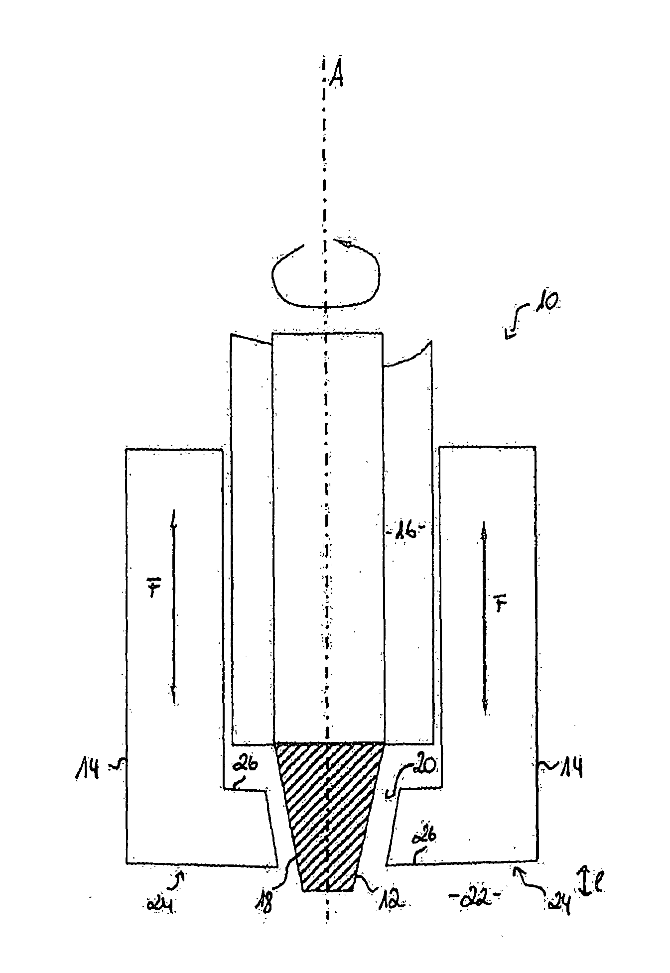
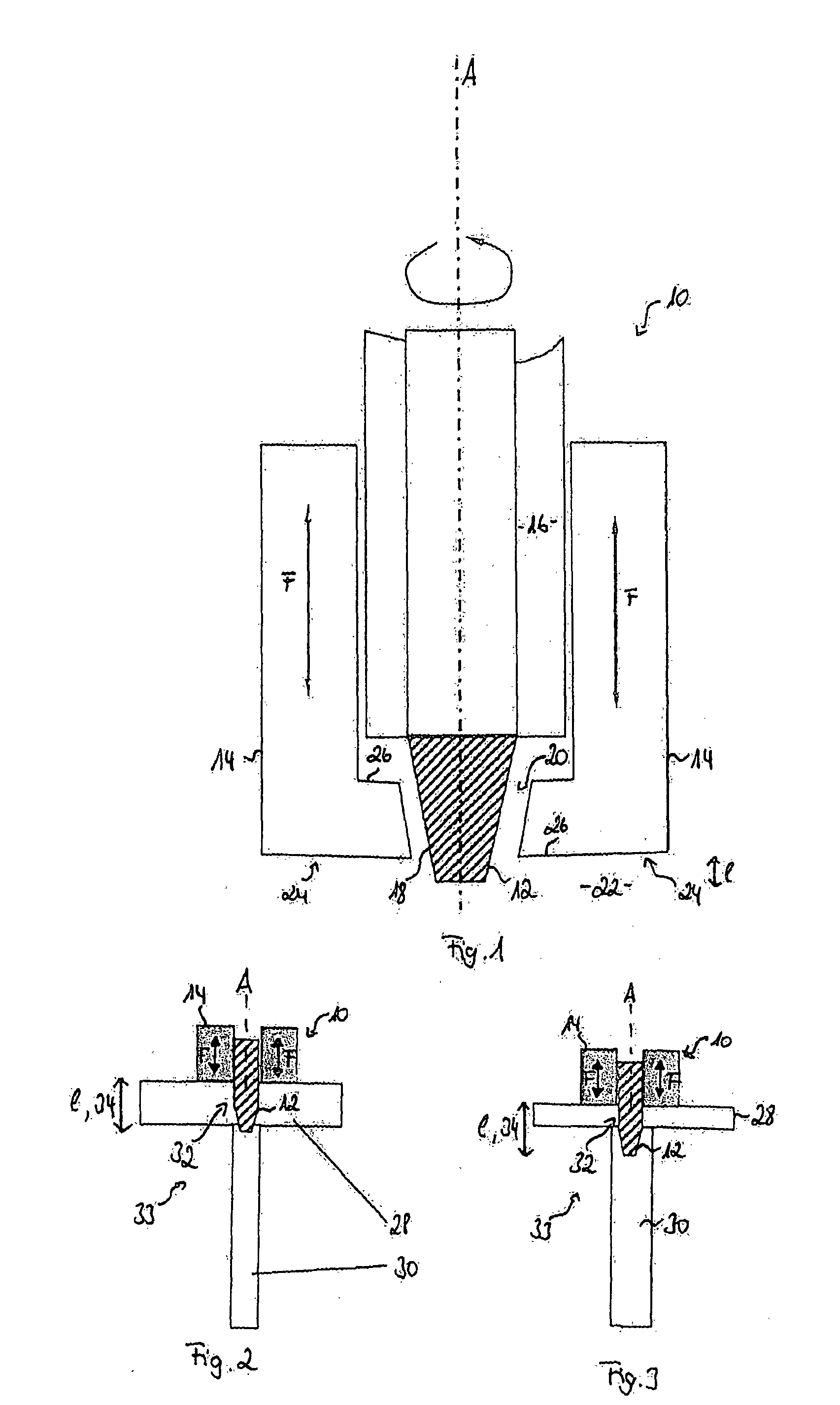
[0036]FIG. 1 is a longitudinal sectional view of a welding tool 10 comprising a tool pin 12 and a shoulder 14.

[0037]The tool pin 12 is attached to a tool pin holder 16, which is mounted in a manner allowing rotation about an axis A in the direction of the arrow.

[0038]In the illustrated embodiment the tool pin holder 16 is designed in the shape of a cylinder; and the tool pin 12 tapers off towards a tool pin end region 18, which projects through a shoulder opening 20 into a surrounding area 22. As a result, the tool pin 12 projects beyond a shoulder end region 24 by a projection I.

[0039]The shoulder 14 is arranged separately from the tool pin holder 16 and is movable along the axis A in the direction of the arrow that is shown.

[0040]The shoulder 14 is configured in essence as a cylinder shape around the axis A and has an L shape in the longitudinal section. In this case, bars 26, which are directed toward the tool pin 12 and which exhibit an L shape in the longitudinal section, are a...

second embodiment

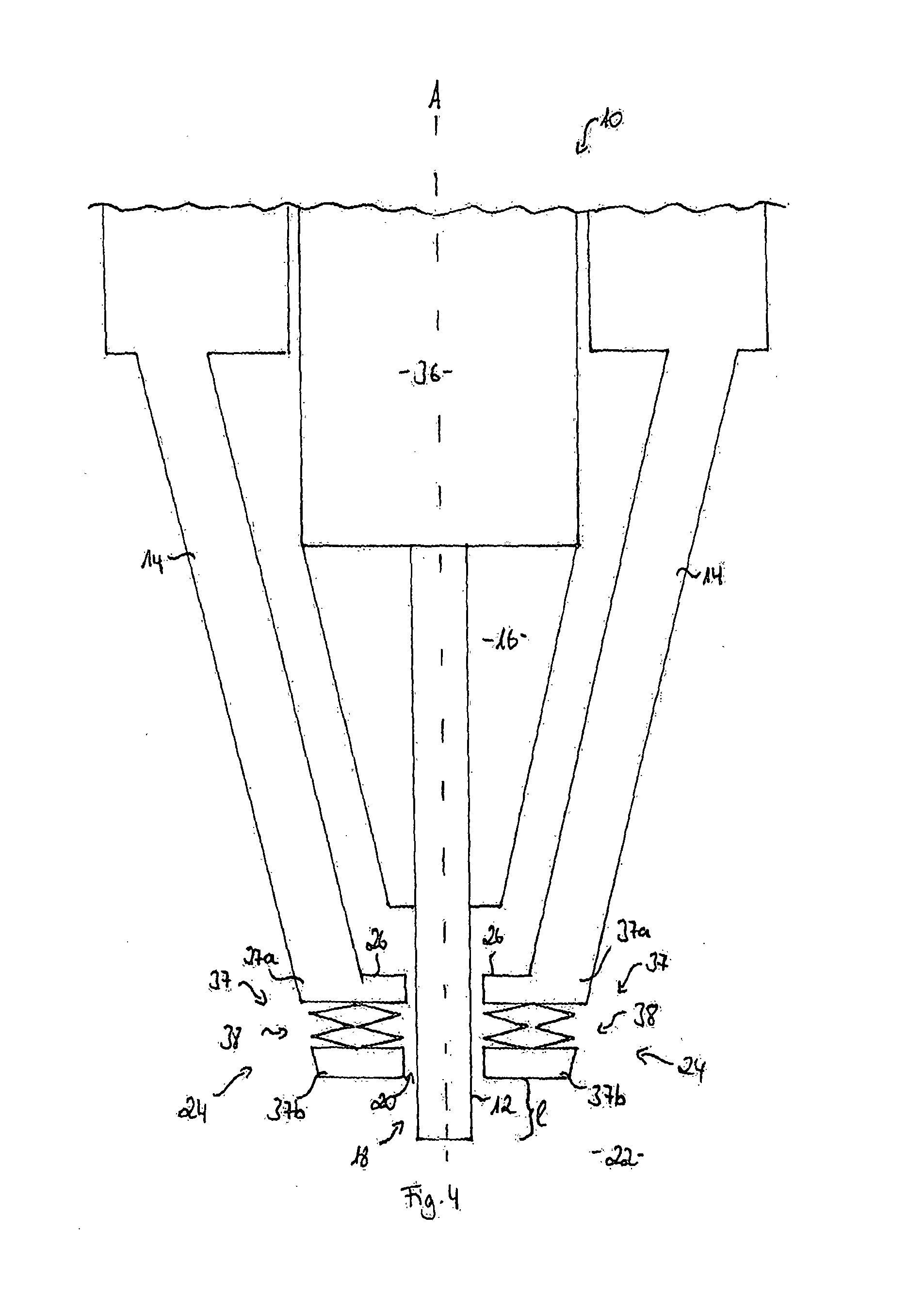
[0043]FIG. 4 shows a welding tool 10.

[0044]In this case the tool pin holder 16 as well as the shoulder 14 are formed in the shape of a cone and taper off towards the shoulder end region 24. With the simultaneous L shaped design of the shoulder 14 in the shoulder end region 24, it is now possible to bring the shoulder 14 especially close to the tool pin 12 and, thus, enable a particularly good isolation of the resulting weld seam from the surrounding area 22.

[0045]In the embodiment that is shown, the shoulder 14 and the tool pin holder 16 are mounted separately from each other. In this case the tool pin holder 16 can be rotated about the axis A. This feature is achieved by means of a spindle 36, on which the tool pin holder 16 is secured.

[0046]The shoulder 14 has an elastic area 37 on the shoulder end region 24, due to the fact that the shoulder end region 24 is divided into two shoulder end subregions 37a, 37b, and a spring arrangement 38 is provided in the space between the shoulde...


PUM

PropertyMeasurementUnit
Shapeaaaaaaaaaa
Areaaaaaaaaaaa

Abstract

A welding tool for joining at least two workpieces at a joining region by friction stir welding includes a tool pin arranged along one axis of the welding tool, for applying frictional heat to the workpieces. The welding tool also includes a shoulder surrounding the tool pin, for separating the joining region from the surrounding area. The shoulder is moveable essentially parallel to the axis of the welding tool.

Description

BACKGROUND AND SUMMARY OF THE INVENTION[0001]Exemplary embodiments of the invention relate to a welding tool for joining at least two workpieces at a joining region by means of friction stir welding.[0002]In contrast to the friction welding process, the friction energy in the friction stir welding process is not generated due to the rotation of one of the two workpieces, which are to be joined, relative to the other workpiece, but rather a wear-resistant welding tool is used. This wear-resistant welding tool applies the rotational energy simultaneously to both workpieces. This process comprises the following steps.[0003]In the first step the welding tool comprising a rotating tool pin is pressed with high force between the two workpieces to be joined, until a shoulder, which surrounds the tool pin and is a part of the welding tool, comes to rest on the surface of the workpieces.[0004]In the second step the rotating tool pin remains for a short period of time at the insertion point, ...

Claims


Application Information

Patent Timeline
IPC IPC(8): B29C65/06B23K20/12
CPCB23K20/1245B29C65/06B23K20/1255B23K20/1265
Inventor SILVANUS, JUERGENFORSTER, ERICHTAUSCHER, ERIC
Owner AIRBUS DEFENCE & SPACE
Why Eureka
Try Eureka