
Stretch laminate

a technology of stretch laminates and stretch, which is applied in the field of stretch laminates, can solve the problems of notoriously difficult and expensive manufacturing of stretch laminates

Inactive Publication Date: 2014-11-06
MONDI GRONAU
View PDF8 Cites 9 Cited by
  • Summary
  • Abstract
  • Description
  • Claims
  • Application Information

AI Technical Summary

Benefits of technology

The patent describes a method for making a laminate that has improved elastic properties. The method involves laminating elastic strips between non-elastic material webs, then stretching the laminate in regions where the elastic strips are present. The resulting laminate can then be used to make items like garments that have elastic properties in specific areas. The elastic strips can be cut and positioned between the non-elastic material webs, and the resulting laminate has better elastic properties compared to non-laminated materials. Reinforcement strips can also be added to strengthen the gaps between the elastic strips.

Problems solved by technology

Complications arise in that stretch laminates are is notoriously difficult and expensive to manufacture.
In particular, a considerable number of patents discuss the difficulties of making these laminates, and the significant and extensive steps that must be undertaken to prepare these laminates.

Method used


Image

  • Stretch laminate
  • Stretch laminate
  • Stretch laminate

Examples


first embodiment

[0088]the method of making a laminate according to the invention is explained below. FIG. 12 schematically shows the method of making an elastic laminate.

[0089]In the method shown in the figure, an elastic film 1 is stretched transverse to a web direction in a preactivation station, and after elastic relaxation is cut into strips 2. The strips 2 are guided over deflectors 3, and as parallel strips are laminated next to one another between two nonwoven material webs 4 and 5. The material webs 4 and 5 are guided above and beneath the strips 2 without prestretching, and are adhesively or thermally bonded to the strips 2. The view clearly shows that the elastic strips 2 are laminated at a spacing from one another between the cover webs, and that the nonwoven cover webs 4 and 5 are directly joined together in the gaps between the elastic strips 2. Elastic regions 6 and inelastic regions 7 are thus formed in the laminate 8. The laminate is supplied to an activation unit 9, in which the la...

second embodiment

[0093]the method will be illustrated in further detail with reference to a similar illustrated embodiment. FIG. 13 is a schematic representation of the second method of making a printed, elastic laminate.

[0094]With the method shown in the FIG. an elastic film 1 is cut into strips 2 that are guided across a deflector 3 and supplied to a laminator 4 as parallel strips. The strips 2 are laminated in the laminator 4 between textile cover webs 5 and 6 that are fed from above and below to the strips 2. The strips 2 and the textile cover webs 5 and 6 are glued together or connected to each other thermally. The view in the figure shows that the elastic strips 2 are laminated at a spacing from each other between the cover webs 5 and 6 and that the textile cover webs 5 and 6 are directly connected to each other in gaps between the elastic strips 2. This way, elastic regions 8 and 10 as well as inelastic regions 9 are created in the laminate 7. The laminate is then supplied to an activator 10 ...


PUM

PropertyMeasurementUnit
Thicknessaaaaaaaaaa
Thicknessaaaaaaaaaa
Thicknessaaaaaaaaaa

Abstract

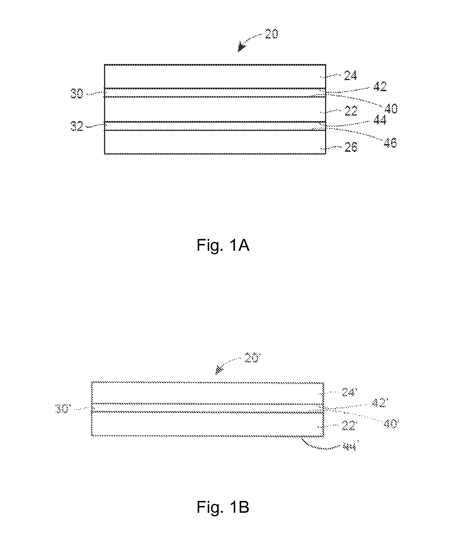
A stretch laminate has at least one cover web, an elastomeric film attached to the cover web and having two opposite faces, and a skin on at least one of the faces. An adhesive at an anchor zone between the skin and the cover web bonds the skin to the cover web at the anchor zone, leaving a stretch zone free of adhesive adjacent the anchor zone. The skin having wrinkles in the anchor zone but not in the stretch zone.

Description

FIELD OF THE INVENTION[0001]The present invention relates to a stretch laminate.BACKGROUND OF THE INVENTION[0002]Stretch laminates form one group of materials commonly used for the production of hygiene articles such as diapers. As the name suggests, these materials are actually composites of individual components that are laminated together, by an adhesive for example. A typical stretch laminate will attempt to combine one or more layers of cover material with one or more layers or strands of an elastomeric material. A stretch laminate may hereafter also be referred to as “elastic laminate” or simply “laminate.”[0003]Complications arise in that stretch laminates are is notoriously difficult and expensive to manufacture. Considerable effort has gone into proposing new types of stretch laminates and new methods of making stretch laminates. In particular, a considerable number of patents discuss the difficulties of making these laminates, and the significant and extensive steps that m...

Claims


Application Information

Patent Timeline
IPC IPC(8): B32B3/26
CPCB32B3/263B32B5/022B32B5/04B32B5/142B32B5/26B32B7/12B32B27/12B32B37/12B32B37/144B32B2038/0028B32B2305/20B32B2307/51B32B2555/02D04H1/593Y10T428/24446
Inventor BALDAUF, GEORGSCHOENBECK, MARCUS
Owner MONDI GRONAU
Learn More