Eureka AIR delivers breakthrough ideas for toughest innovation challenges, trusted by R&D personnel around the world.

Exhaust system for an off-road vehicle

a technology for exhaust systems and off-road vehicles, applied in the direction of engines, mechanical equipment, machines/engines, etc., can solve the problems of inability to monitor the emissions of exhaust gas sensors, and inability to meet the requirements of exhaust system efficiency, so as to reduce the efficiency of exhaust system and increase the wear of exhaust components

Active Publication Date: 2014-11-13
BLUE LEAF I P INC
View PDF16 Cites 19 Cited by
  • Summary
  • Abstract
  • Description
  • Claims
  • Application Information

AI Technical Summary

Benefits of technology

The patent text describes an exhaust system for off-road vehicles that includes an outlet port and an outlet stack with a gap between them. The system also has an exhaust shield with an opening and an electronic control unit (ECU) placed inside the gap. The gap creates an airflow path for cooling the ECU. The technical effect of this system is to cool the ECU more effectively while still maintaining the necessary flow of exhaust gas for off-road vehicles.

Problems solved by technology

As a result, the ECU may be located within an undesirably hot region of the exhaust system.
In addition, the sensors used to monitor the emissions in the exhaust gas may be susceptible to moisture.
For example, water (e.g. from rain) that enters the exhaust stack may contact the sensor, thereby interfering with emissions measurements.
Furthermore, foreign debris may build up within the exhaust system, thereby interfering with airflow configured to cool the exhaust system.
As a result, certain portions of the exhaust system may become undesirably hot.
Exhaust system overheating may increase wear on exhaust components and / or reduce exhaust system efficiency.

Method used


Image

  • Exhaust system for an off-road vehicle
  • Exhaust system for an off-road vehicle
  • Exhaust system for an off-road vehicle

Examples


Embodiment Construction

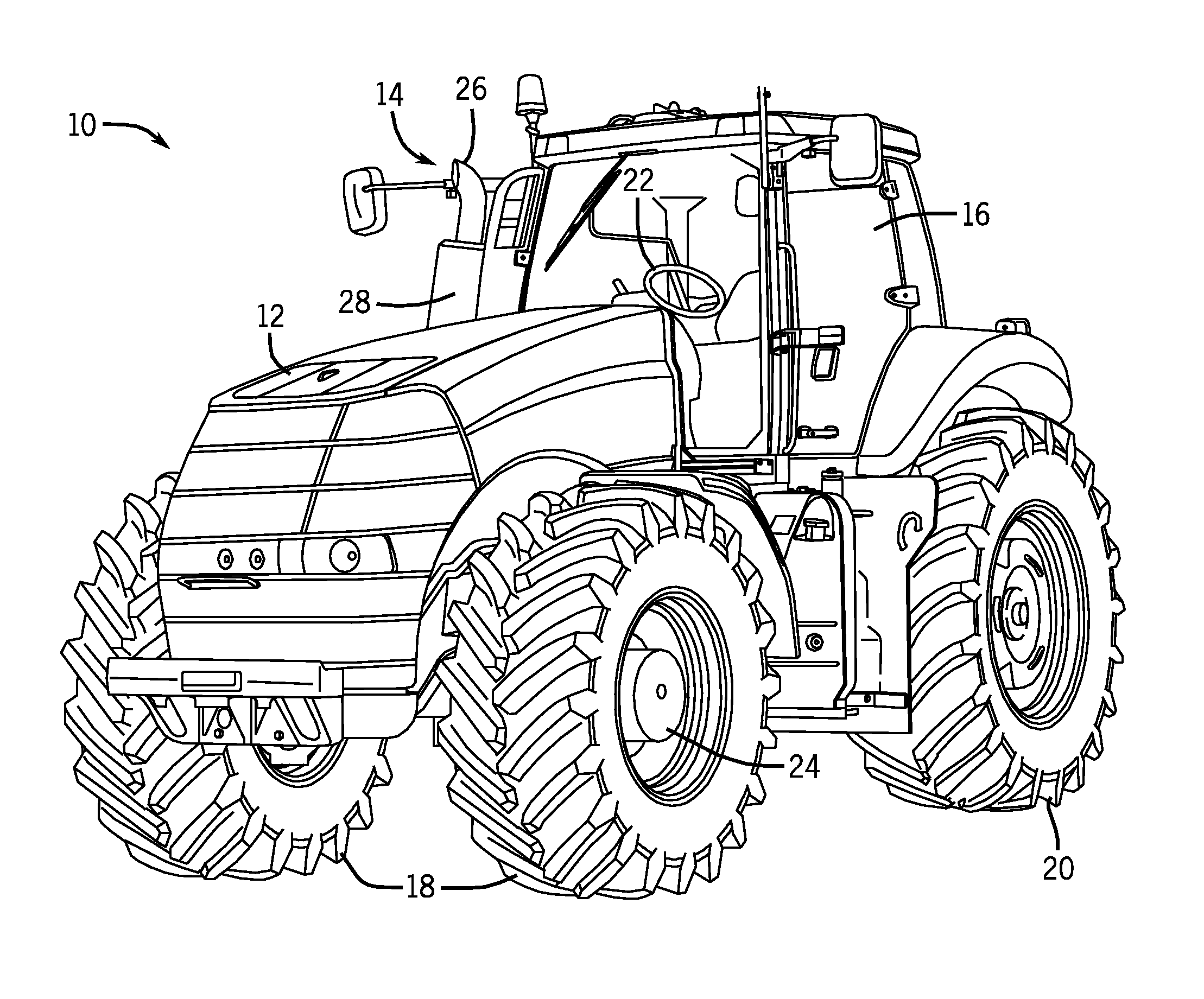
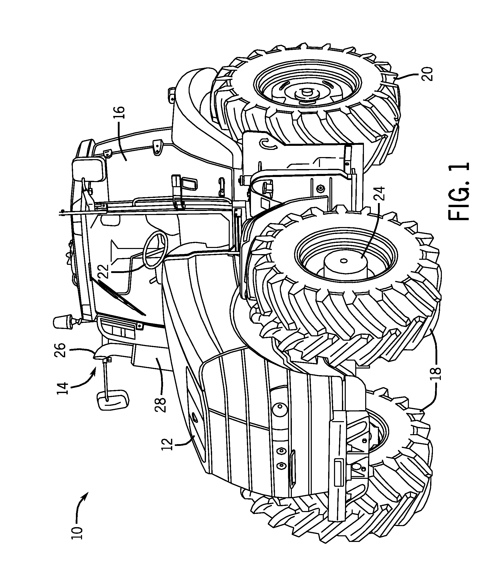
[0016]One or more specific embodiments of the present disclosure will be described below. In an effort to provide a concise description of these embodiments, all features of an actual implementation may not be described in the specification. It should be appreciated that in the development of any such actual implementation, as in any engineering or design project, numerous implementation-specific decisions must be made to achieve the developers' specific goals, such as compliance with system-related and business-related constraints, which may vary from one implementation to another. Moreover, it should be appreciated that such a development effort might be complex and time consuming, but would nevertheless be a routine undertaking of design, fabrication, and manufacture for those of ordinary skill having the benefit of this disclosure.

[0017]When introducing elements of various embodiments of the present disclosure, the articles “a,”“an,”“the,” and “said” are intended to mean that th...


PUM


Abstract

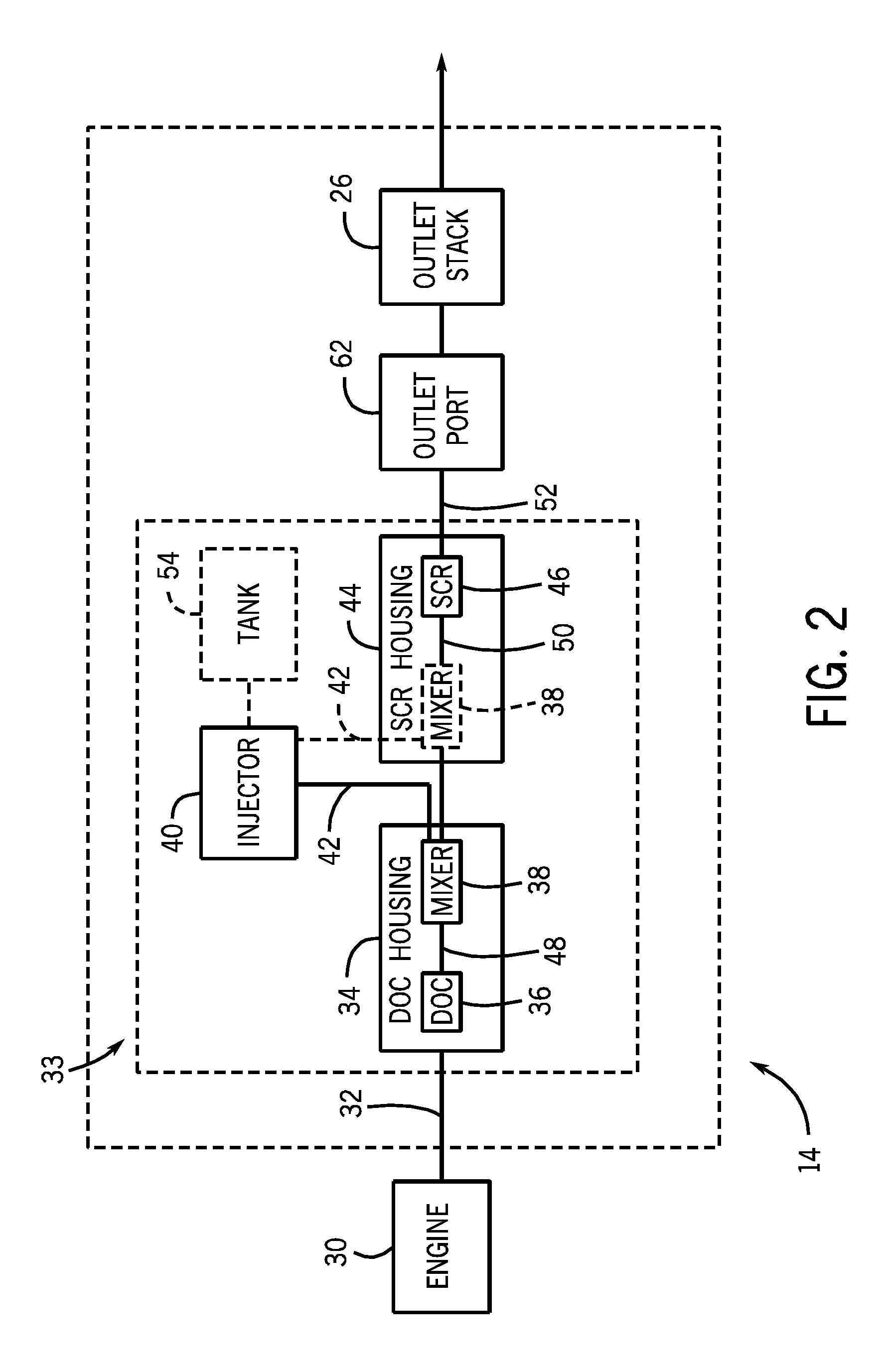
An exhaust system for an off-road vehicle including an outlet port configured to release exhaust gas and an outlet stack disposed about the outlet port, in which at least a portion of the outlet stack is radially spaced from the outlet port to form a gap between the outlet stack and the outlet port. The outlet stack is configured to direct a flow of exhaust gas from the outlet port toward a distal end of the outlet stack. The exhaust system further includes an exhaust shield in close proximity or coupled to the outlet stack comprising at least one opening and an electronic control unit (ECU) disposed within the exhaust shield. The gap is configured to establish an airflow path from the at least one opening to a region of the outlet stack downstream from the outlet port, and the ECU is positioned within the airflow path between the at least one opening and the gap to facilitate cooling of the ECU.

Description

CROSS REFERENCE TO RELATED APPLICATION[0001]This application claims priority from and the benefit of U.S. Provisional Patent Application Ser. No. 61 / 732,073, entitled “EXHAUST SYSTEM FOR AN OFF-ROAD VEHICLE”, filed Nov. 30, 2012, which is hereby incorporated by reference in its entirety.BACKGROUND[0002]The present disclosure relates generally to off-road vehicles with diesel engines, and more particularly, to an exhaust system configured to direct an exhaust flow away from the diesel engine.[0003]Certain off-road vehicles are powered by diesel engines and produce exhaust gas. The exhaust gas may include undesirable byproducts such as nitrogen oxides (NOx), carbon monoxide, and particulate material. Government regulations have continually reduced the acceptable concentrations of these byproducts, specifically in relation to NOx and NH3. Certain off-road vehicles include an exhaust system that monitors the concentration of the byproducts via sensors positioned within the exhaust syste...

Claims


Application Information

Patent Timeline
Patent Type & Authority Applications(United States)
IPC IPC(8): F01N13/08
CPCF01N13/08F01N2900/00F01N2470/00F01N3/2066F01N13/008F01N13/082F01N13/085F01N2260/022F01N2260/20F01N2270/02F01N2560/021F01N2560/026F01N2590/08Y02A50/20F01N3/2892F01N2560/028F01N2260/26F01N2470/24F01N3/05F01N3/10F01N2560/02F01N2470/02F01N2470/30F01N2470/08F01N2240/20F01N3/038F01N3/035F01N2270/08
Inventor ADUPALA, RAJESHWAR R.MOREY, DANIEL A.SCHROEDER, WILLIAM
Owner BLUE LEAF I P INC
Why Eureka
Eureka Blog
Learn More