Supercharge Your Innovation With Domain-Expert AI Agents!

Intrawell Fluid Injection System and Method

a fluid injection system and fluid technology, applied in the field of intrawell fluid injection system and method, can solve the problems of still requiring surface processing and testing of the produced water, and achieve the effect of preventing reverse flow

Inactive Publication Date: 2014-11-13
HALLIBURTON ENERGY SERVICES INC
View PDF19 Cites 3 Cited by
  • Summary
  • Abstract
  • Description
  • Claims
  • Application Information

AI Technical Summary

Benefits of technology

The patent describes a method for controlling fluid injection in a well. This involves using a check valve to prevent fluid from flowing back through the system, measuring the flow of fluid with a sensor, and separating gas from the fluid before it reaches the wellhead. These technical methods help to improve the operation of the well and increase the production of oil or gas.

Problems solved by technology

It has been found, however, that the reinjection of the produced water into a neighboring well still requires surface processing and testing of the produced water.

Method used


Image

  • Intrawell Fluid Injection System and Method
  • Intrawell Fluid Injection System and Method
  • Intrawell Fluid Injection System and Method

Examples


Embodiment Construction

[0020]While the making and using of various embodiments of the present invention are discussed in detail below, it should be appreciated that the present invention provides many applicable inventive concepts, which can be embodied in a wide variety of specific contexts. The specific embodiments discussed herein are merely illustrative of specific ways to make and use the invention, and do not delimit the scope of the present invention.

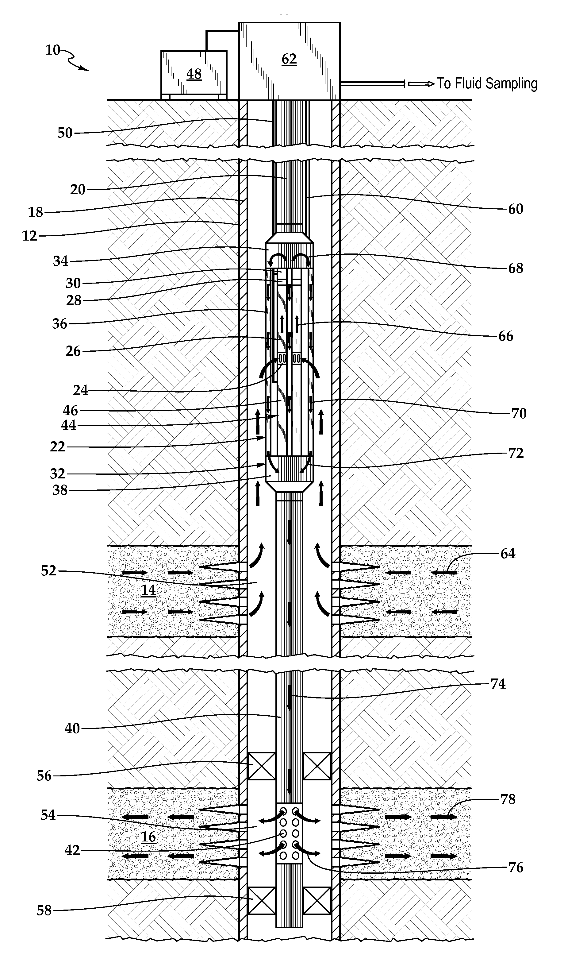
[0021]Referring initially to FIG. 1, an intrawell fluid injection system positioned in a well is schematically illustrated and generally designated 10. A wellbore 12 extends through the various earth strata including formation 14 and formation 16. A casing 18 is secured within wellbore 12. A tubing string 20 is disposed within wellbore 12. Tubing string 20 includes various tools for controlling fluid flow in wellbore 12 such as intrawell fluid injection system 22. In the illustrated embodiment, intrawell fluid injection system 22 includes a fluid intak...


PUM


Abstract

An intrawell fluid injection system is operably positionable in a well having a production zone that is in fluid isolation from a discharge zone. The system includes an electric submersible pump assembly having an electric motor and a fluid pump that is operably associated with the electric motor. The fluid pump has a fluid intake operably positionable in fluid communication with the production zone. The fluid pump is operable to pump formation fluid from the production zone in a first axial direction. The system also includes a bypass assembly that is in downstream fluid communication with the electric submersible pump assembly. The bypass assembly is operable to transport formation fluid from the electric submersible pump assembly in a second axial direction that is opposite the first axial direction. The bypass assembly has a fluid discharge operably positionable in fluid communication with the discharge zone.

Description

CROSS-REFERENCE TO RELATED APPLICATIONS[0001]This application claims the benefit under 35 U.S.C. §119 of the filing date of International Application No. PCT / US2013 / 039951, filed May 7, 2013.TECHNICAL FIELD OF THE INVENTION[0002]This invention relates, in general, to equipment utilized in conjunction with operations performed in relation to subterranean wells and, in particular, to the use of an intrawell fluid injection system to inject fluid from a production zone into a discharge zone without surfacing the fluid.BACKGROUND OF THE INVENTION[0003]Without limiting the scope of the present invention, its background is described with reference to producing water from a hydrocarbon bearing subterranean formation, as an example.[0004]Most hydrocarbon bearing subterranean formations produce a mixture of oil and / or gas together with water, usually in the form of brine which may contain large amounts of dissolved minerals or precipitates such as salts. In fact, in some wells, water and oth...

Claims


Application Information

Patent Timeline
Patent Type & Authority Applications(United States)
IPC IPC(8): E21B43/16
CPCE21B43/162E21B43/128E21B43/14
Inventor BASSETT, LONNIE GENE
Owner HALLIBURTON ENERGY SERVICES INC
Features
  • R&D
  • Intellectual Property
  • Life Sciences
  • Materials
  • Tech Scout
  • Unparalleled Data Quality
  • Higher Quality Content
  • 60% Fewer Hallucinations
Learn More