

Observation system and method of controlling observation system
- Summary
- Abstract
- Description
- Claims
- Application Information
AI Technical Summary
Benefits of technology
Problems solved by technology
Method used
Image

Examples
first embodiment
General Configuration
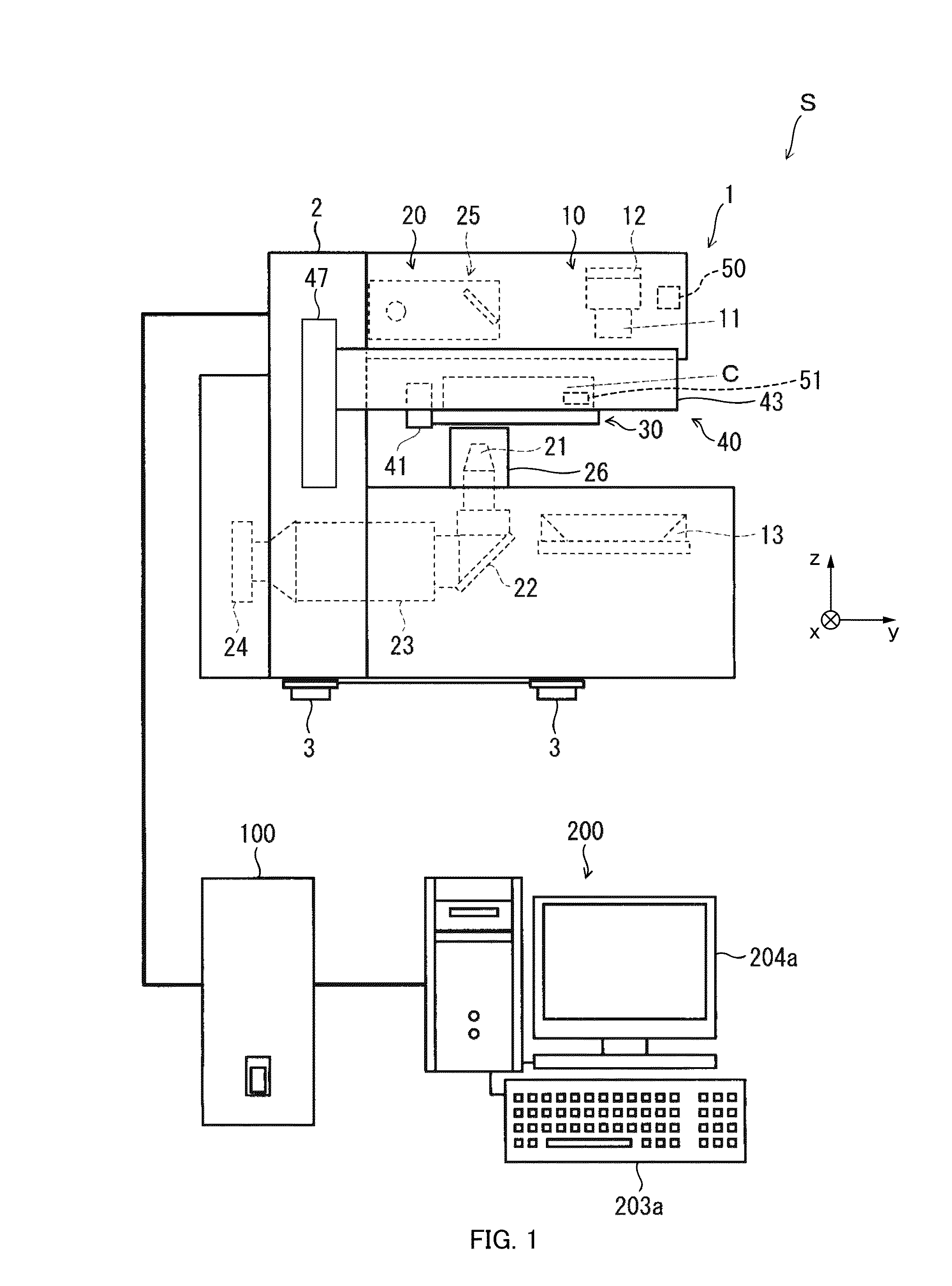
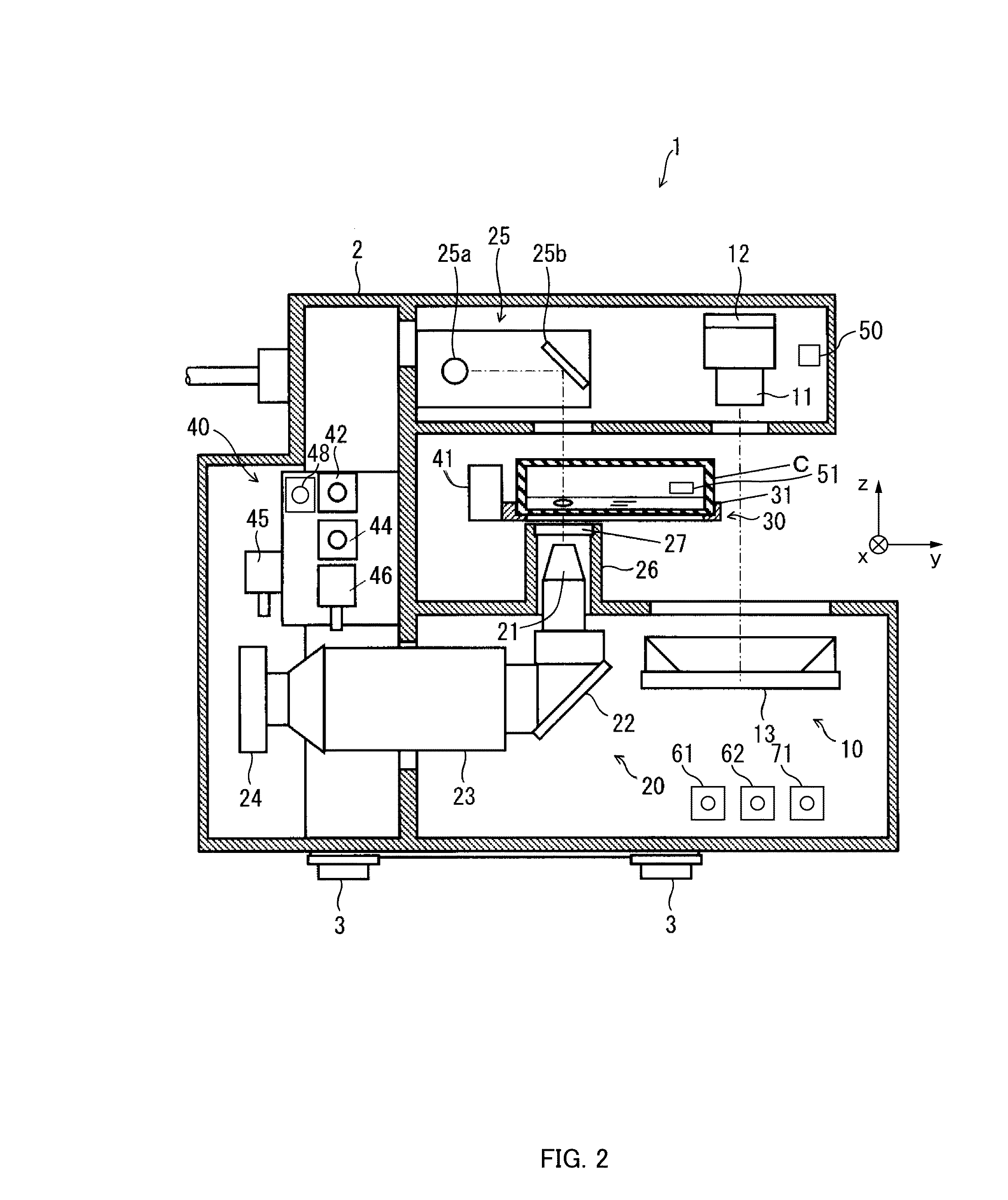
[0050]An observation system S according to a first embodiment of the present disclosure will be described with reference to FIGS. 1 to 11. FIG. 1 is a general configuration diagram illustrating the observation system S, FIG. 2 is a perpendicular sectional side view illustrating an observation apparatus 1 included in the observation system S, FIG. 3 is a perpendicular sectional front view illustrating the observation apparatus 1, FIG. 4 is a perpendicular sectional side view illustrating the observation apparatus 1, and FIG. 5 is a diagram illustrating an illumination unit 17. FIGS. 6 and 7 are diagrams illustrating an inner diameter light-shielding plate drive mechanism 60. FIG. 8 is a diagram illustrating an outer diameter light-shielding plate drive mechanism 70. FIG. 9 is a diagram illustrating a diffusion plate 80. FIG. 10 is a block diagram illustrating a configuration of a computer 200 included in the observation system S. FIG. 11 is a diagram illustrating...
experimental examples
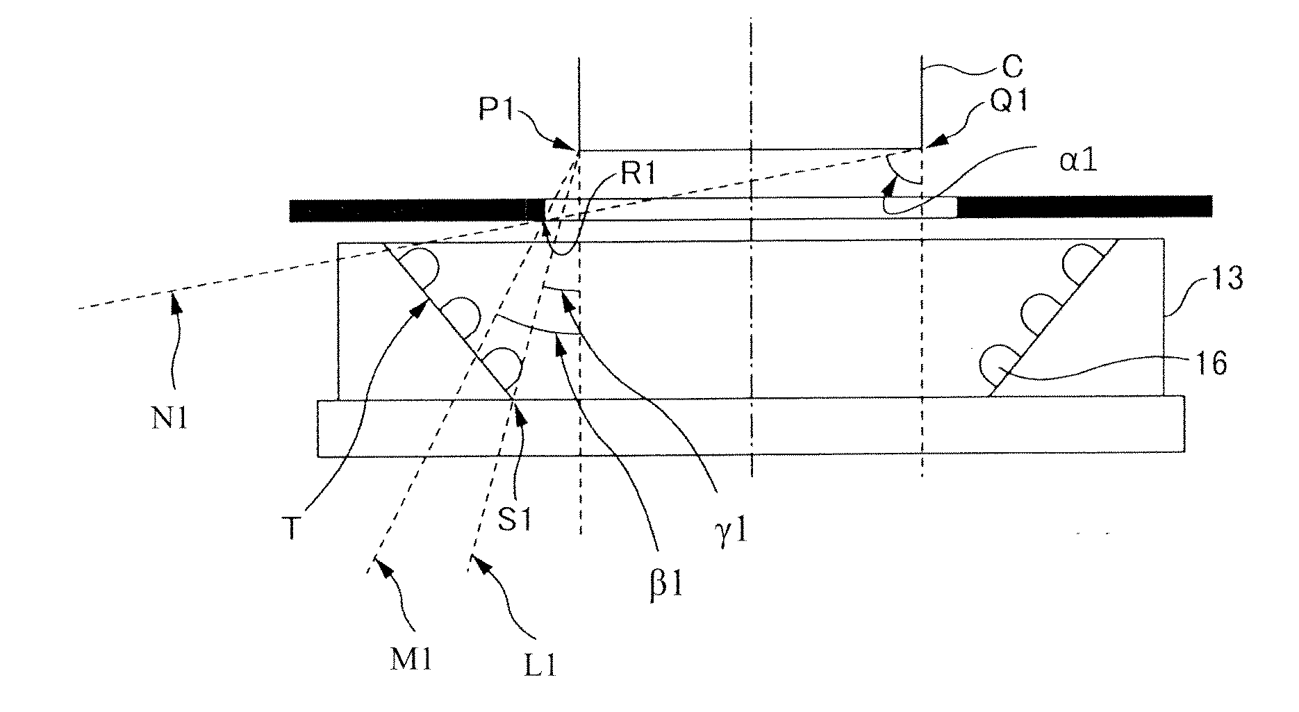
[0244]Next, FIGS. 21 and 22 illustrate experimental examples in the case where the bottom surface of the container C is illuminated by the ring illumination 13, using the observation system S according to an embodiment of the present disclosure.
[0245]The ring illumination 13 used for the experiments is LDR2-100SW2-LA manufactured by CCS Inc., and is configured such that 60 white LEDs 16 in each circle are aligned in three rows on an inclined surface in a ring shape facing inward and diagonally upward. This ring illumination 13 has an outer diameter of 100 millimeters, an inner diameter of 70 millimeters, and a height of 22 millimeters.
[0246]Further, the container C used for the experiments is a culture container having an outer diameter of 60 millimeters.
[0247]Further, the CMOS camera 12 used for the experiments is of a 1 / 2.5-inch format and the lens 11 has a focal length of 9 millimeters.
[0248]The experiments have been performed with the distance between the lens 11 and the bottom ...
second embodiment
[0268]Next, a description will be given of a configuration of the observation system S according to a second embodiment of the present disclosure with reference to FIG. 25. FIG. 25 is a configuration diagram of the observation system S. Note that since a basic configuration of an embodiment of the present disclosure is the same as that of the aforementioned first embodiment described with reference to FIGS. 1 to 24, the same reference numerals are given to the constituent elements common to those in the first embodiment, and the figures and the descriptions thereof will be omitted.
[0269]The observation apparatus 1 of the observation system S according to a second embodiment of the present disclosure is included in the interior of an incubator 300, as illustrated in FIG. 25. The incubator 300 is an example of a storage case for culturing or storing a cell, and forms a biologically and physically sealed storage space E. The observation apparatus 1 is installed on a shelf 301 provided ...
PUM
 Abstract
Description
Claims
Application Information