Low shading loss solar module

a solar module and low shading technology, applied in the field of solar cell modules, can solve the problems of shading loss, difficult automation of final backside cell and module processing, potential yield limitation, etc., and achieve the effect of reducing the shading of the front side, reducing the cost of solar cell and module fabrication, and high aspect ratio tabs

Inactive Publication Date: 2014-11-20
CRYSTAL SOLAR INC
View PDF7 Cites 5 Cited by
  • Summary
  • Abstract
  • Description
  • Claims
  • Application Information

AI Technical Summary

Benefits of technology

[0007]The present invention provides a solar cell with a transparent handle, wherein the handle includes grooves/slots into which tabs are inserted, enabling the use of high aspect ratio tabs which reduce the shading of the front side of the solar cell when compared to conventional low aspect ratio tabs. Electrical connection of the tabs to busbars on the surface of the solar cell is through apertures at the bottom of each groove on the transparent handle—the grooves being aligned to the busbars. The apertures may be filled with solder, metal pins, metal spheres or other electrically c

Problems solved by technology

The challenge with this approach has been to process these thin silicon substrates (less than 50 microns thick) with high yield and yet preserve the ability to make high efficiency cells, such as cells with selective emitter formation on the front side and point contacts (as in PERC and PERL cells) on the back side.
However, such an approach requires tabbing of the thin epitaxial cells before attaching the cells to the handle; this step can be potentially yield limiting since the tabs are typically 200 microns thick and tend to stress the epitaxial layer which is typically only 50 microns thick.
Furthermore, the presence of tabs, sticking out beyond the silicon and glass, during the back side processing makes the final backside cell and module processing

Method used


Image

  • Low shading loss solar module
  • Low shading loss solar module
  • Low shading loss solar module

Examples


Embodiment Construction

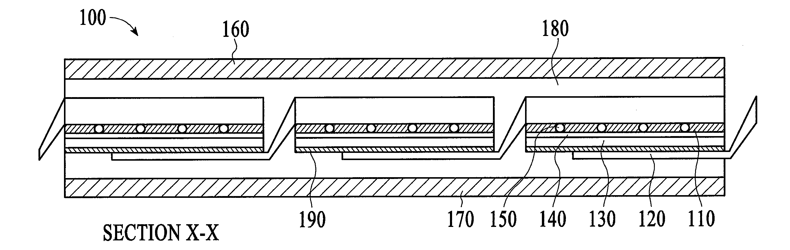
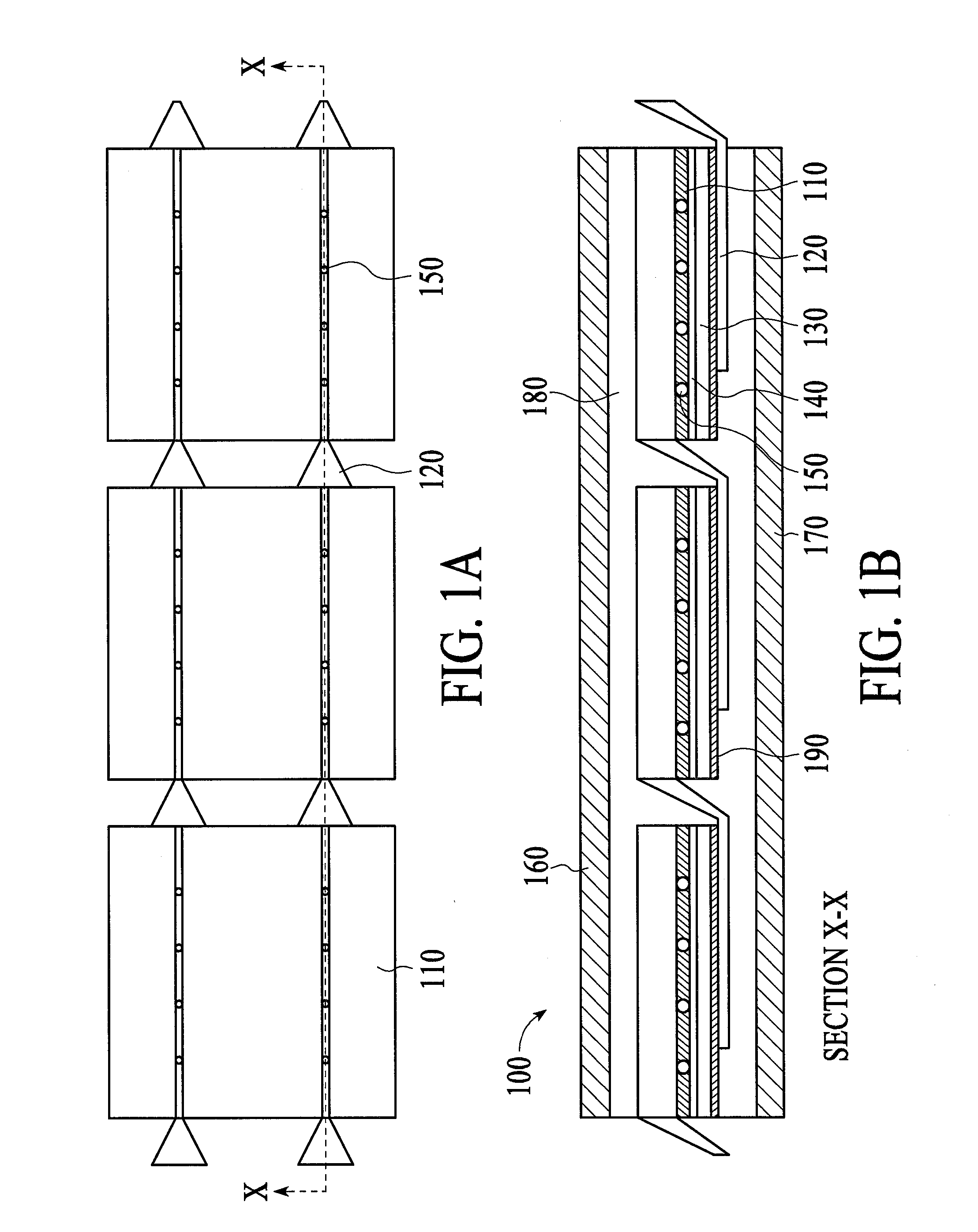
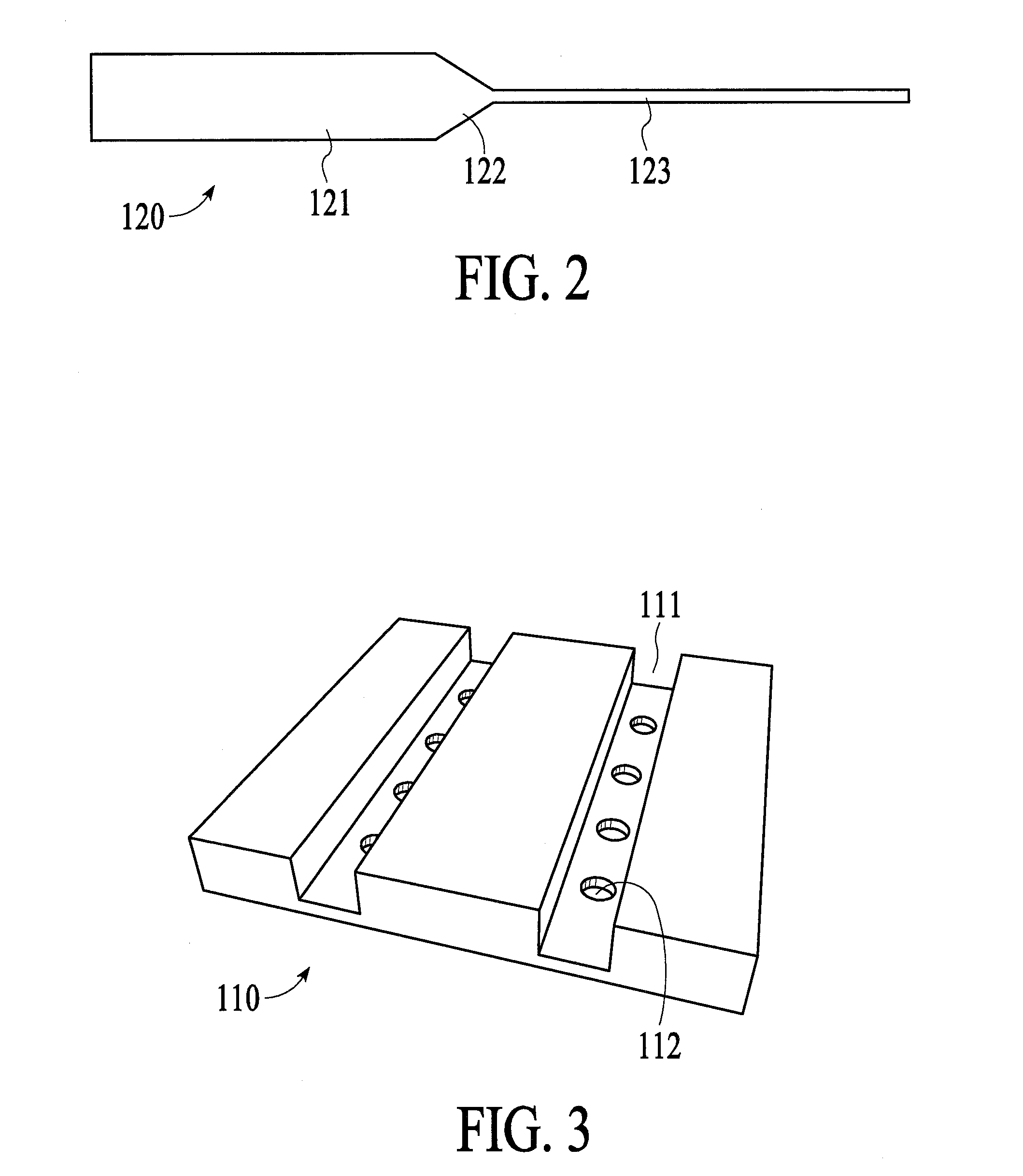
[0020]Embodiments of the present invention will now be described in detail with reference to the drawings, which are provided as illustrative examples of the invention so as to enable those skilled in the art to practice the invention. Notably, the figures and examples below are not meant to limit the scope of the present invention to a single embodiment, but other embodiments are possible by way of interchange of some or all of the described or illustrated elements. Moreover, where certain elements of the present invention can be partially or fully implemented using known components, only those portions of such known components that are necessary for an understanding of the present invention will be described, and detailed descriptions of other portions of such known components will be omitted so as not to obscure the invention. In the present specification, an embodiment showing a singular component should not be considered limiting; rather, the invention is intended to encompass ...


PUM


Abstract

A solar cell comprises an optically transparent handle, wherein the handle includes grooves into which tabs are inserted, enabling the use of high aspect ratio tabs with minimal shading of the front side of the solar cell. Electrical connection of the tabs to busbars on the surface of the layers of the solar cell is through apertures at the bottom of each groove on the handle—the grooves being aligned to the busbars. The apertures may be filled with solder, metal pins, metal spheres, etc, and in embodiments the tabs may be metal wires. The solar cells with optically transparent handles may be formed into solar cell modules. Furthermore, in embodiments the handle with integral tabs simplifies and reduces the cost of solar cell and module fabrication since the top surface of the transparent handle including tabs may be completely flat.

Description

CROSS-REFERENCE TO RELATED APPLICATIONS[0001]This application claims the benefit of U.S. Provisional Application No. 61 / 777,891 filed Mar. 12, 2013, and U.S. Provisional Application No. 61 / 961,233 filed Oct. 7, 2013, both incorporated herein by reference in their entirety.FIELD OF THE INVENTION[0002]The present invention relates generally to silicon solar cell modules, and more particularly to solar modules with front side glass and tabs configured for low shading loss,BACKGROUND[0003]Thin silicon using epitaxy and lift-off is very attractive as a next generation technology since it represents a polysilicon-less, ingot-less and kerf-less approach to making mono-crystalline solar cells. The challenge with this approach has been to process these thin silicon substrates (less than 50 microns thick) with high yield and yet preserve the ability to make high efficiency cells, such as cells with selective emitter formation on the front side and point contacts (as in PERC and PERL cells) on...

Claims


Application Information

Patent Timeline
IPC IPC(8): H01L31/02H01L31/18
CPCH01L31/1804H01L31/0201H01L31/022433H01L31/0508H01L31/0547Y02E10/52Y02E10/547
Inventor RAVI, TIRUNELVELI S.
Owner CRYSTAL SOLAR INC
Why Eureka
Try Eureka