Lens Barrel

a barrel and lens technology, applied in the field of optical products, can solve the problems of thermal expansion and refractive index change, and increase in deterioration of optical properties, and achieve the effect of high performan

Inactive Publication Date: 2014-11-20
JCD GUANG ZHOU OPTICAL
View PDF9 Cites 32 Cited by
  • Summary
  • Abstract
  • Description
  • Claims
  • Application Information

AI Technical Summary

Benefits of technology

[0006]In view of the above problems existing in the old technology, the object of the present invention is to provide a small, low-cost and high-performance lens barrel.
[0008]Hence, by increasing or decreasing the space in the optical axis direction between the lenses at both ends of the elastic member, the variation in the focal position of the lens barrel is suppressed, thereby solving the above problem.
[0010]As long as the linear expansion coefficient of the material of the lens chamber is different from that of the lens group, two lenses at both ends of a compressed spring will be moved under the action of the compressed spring when temperature changes, causing the distance between the two lenses to be increased or shortened. By making the linear expansion coefficient of the material of the lens chamber greater than that of the lens group, the distance between the two lenses at both ends of the compressed spring can be increased or shortened in a direction that helps to cancel a variation in the back focus of the lens barrel caused by a variation in the refractive index of the lens resulting from a temperature change.
[0012]That the variation in the focal position of the lens barrel is greater than (equal to or greater than) the variation in the distance between the lenses can suppress the influence produced by the variation in the focal position of the lens barrel caused by the variation in the refractive index of the lens when the temperature undergoes a big change.
[0014]With the lens chamber formed of plastic material, the lens chamber can have an appropriate thermal expansion coefficient and thus can suppress the influence produced by the variation in the back focus of the lens barrel caused by the variation in the refractive index of the lens when the temperature changes.
[0016]That the lens group at least includes one or more plastic lenses makes it easy to set the thermal expansion coefficient of the entire lens group to be in coordination with the thermal expansion coefficient of the lens chamber so that it is possible to better suppress the influence produced by the variation in the back focus of the lens barrel caused by the variation in the refractive index of the lens when the temperature changes.

Problems solved by technology

In the past, people were aware of the existence of the following problem: thermal expansion of the lens and the lens chamber and the change of the refractive index of the lens resulting from a temperature change cause the focal position of the lens barrel to change and thus deteriorates the optical property.
In particular, when a part of the lens or the lens chamber is formed of plastic material, the thermal expansion and the change of refractive index become larger and the deterioration of the optical property becomes larger.
The problem of deterioration of the optical property can be solved by providing a mechanism (e.g. an automatic focusing mechanism) which suppresses a variation in the focal position of the lens barrel, but the size of the lens barrel will become bigger and the manufacturing cost will be increased.
Furthermore, even if the lens barrel has an automatic zoom mechanism therein, when the focal position of the lens barrel varies as the temperature changes, the control range of the automatic focusing mechanism becomes larger, as a result, the increase in the size of the lens barrel is still inevitable
In this case, the optical property of the lens barrel deteriorates and the performance of the lens barrel at the normal temperature cannot be maintained.
However, such a mechanism will cause an increase in the size and the manufacturing cost of the lens barrel.

Method used


Image

  • Lens Barrel
  • Lens Barrel
  • Lens Barrel

Examples


first embodiment

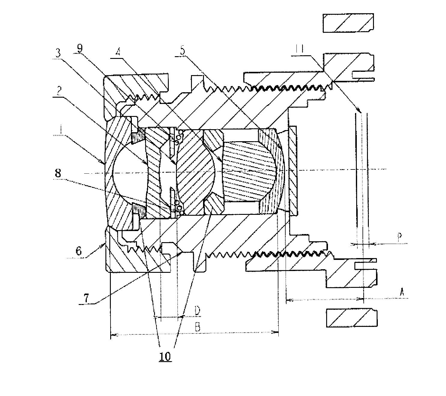
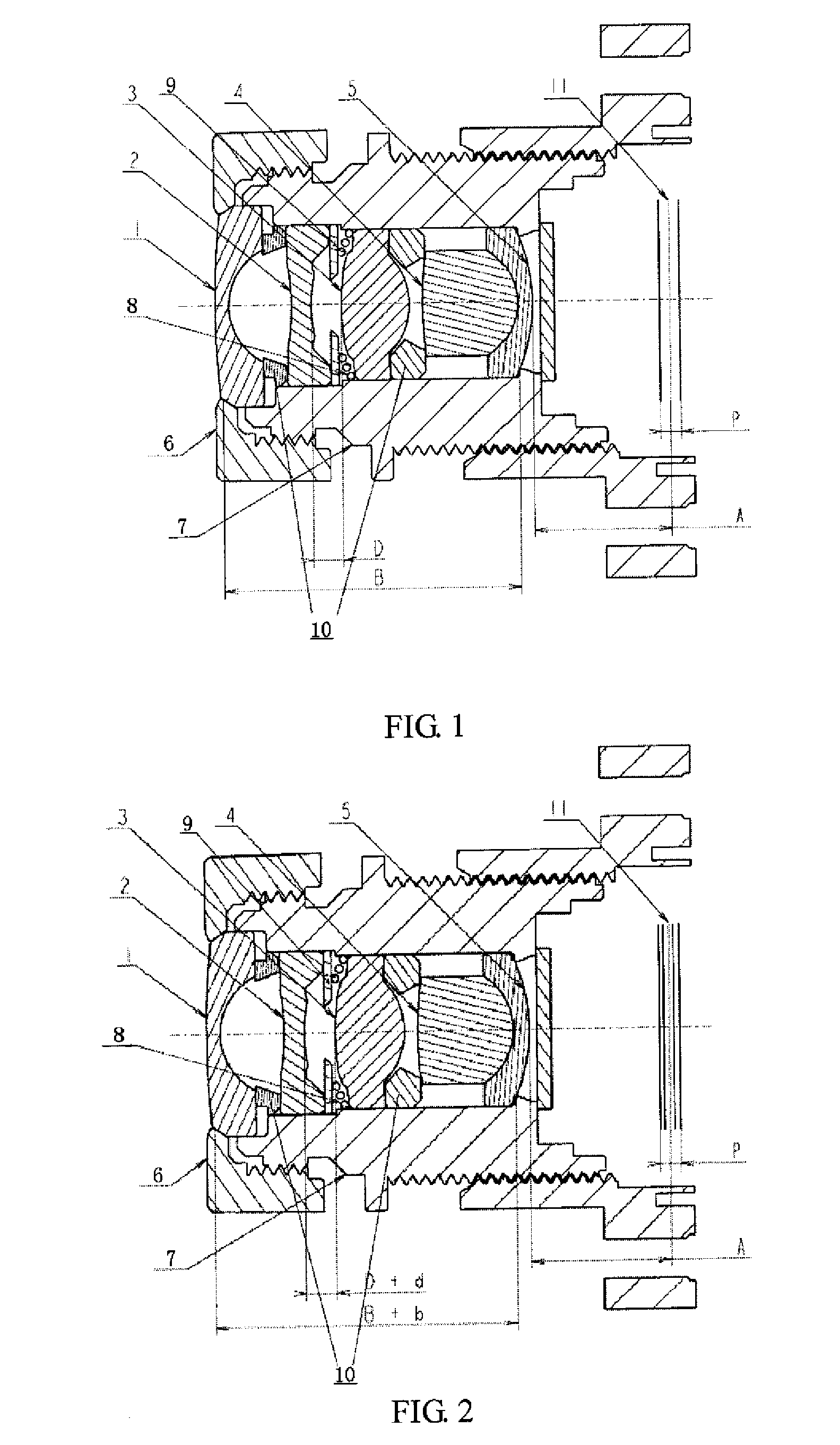
[0029]the present invention will be described with reference to FIGS. 1 and 2.

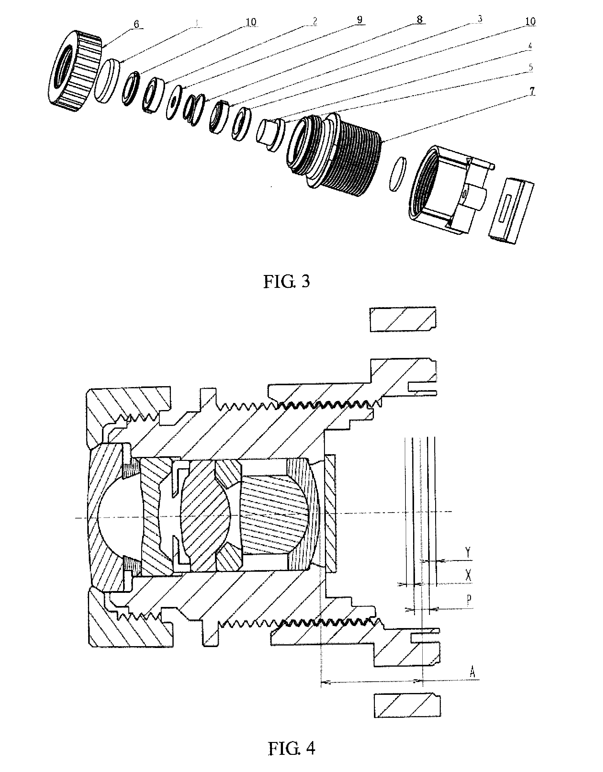
[0030]A lens barrel of the present invention comprises: a plastic pressing ring 6, a plastic lens chamber 7, 1st-5th lenses 1-5 held in the plastic lens chamber 7, a compressed spring 8 disposed between the second lens 2 and the third lens 3 for urging in a direction such that the second lens 2 and the third lens 3 are separated from each other in opposite directions, a parallel spacer 9, and spacers 10 for positioning two adjacent sets of lenses in the optical axis direction. The lens groups 1-5 and the spacers 10 are urged by the compressed spring 8 in the optical axis direction so as to receive appropriate load pressures. The plastic lens chamber 7, the plastic pressing ring 6, the lens groups 1-5 and the spacers 10 have different linear expansion coefficients. As the temperature changes, the size of each component changes to accumulate to form a difference value. Under the action of the compressed spri...


PUM


Abstract

The present invention provides a lens barrel applicable to digital cameras, image pickup devices and cell phones. The lens barrel is small, low-cost and high-performance, and can suppress, by means of a simple mechanism provided in the lens barrel, a variation in the focal position of the lens barrel caused by the change in temperature. The lens barrel comprises a lens group consisting of a plurality of lenses and a lens chamber for holding the lens group. An elastic member is provided between a set of adjacent lenses of the lens group, for urging the set of adjacent lenses in an optical axis direction of the lenses. The space between the set of lenses is increased or decreased by the elastic member, which causes a back focus of the lens barrel to move in a direction opposite to the direction in which the focal position of the lens barrel varies due to thermal expansion or thermal contraction of the lens group and the lens chamber and the change of refractive index of the lens group resulting from a temperature change. Hence, by increasing or decreasing the space in the optical axis direction between the lenses at both ends of the elastic member, the variation in the focal position of the lens barrel is suppressed.

Description

FIELD OF THE INVENTION[0001]The present invention relates to the field of optical products, and in particular relates to a small, low-cost and high-performance lens barrel.DESCRIPTION OF THE RELATED ART[0002]In the past, people were aware of the existence of the following problem: thermal expansion of the lens and the lens chamber and the change of the refractive index of the lens resulting from a temperature change cause the focal position of the lens barrel to change and thus deteriorates the optical property. In particular, when a part of the lens or the lens chamber is formed of plastic material, the thermal expansion and the change of refractive index become larger and the deterioration of the optical property becomes larger.[0003]The problem of deterioration of the optical property can be solved by providing a mechanism (e.g. an automatic focusing mechanism) which suppresses a variation in the focal position of the lens barrel, but the size of the lens barrel will become bigge...

Claims


Application Information

Patent Timeline
Patent Type & Authority Applications(United States)
IPC IPC(8): G02B7/02
CPCG02B7/028
Inventor WAKABAYASHI, HIROSHIKANO, TAKEHIROCHEN, BO
Owner JCD GUANG ZHOU OPTICAL
Why Eureka
Try Eureka