Inverter device

a technology of inverter device and inverter, which is applied in the direction of ac-dc conversion, power conversion system, electrical apparatus, etc., can solve the problems of major increase in the cost of semiconductor elements or other passive components, and achieve the effect of reducing the cost of the inverter devi

Active Publication Date: 2015-04-07
MURATA MFG CO LTD
View PDF10 Cites 8 Cited by
  • Summary
  • Abstract
  • Description
  • Claims
  • Application Information

AI Technical Summary

Benefits of technology

[0008]Accordingly, preferred embodiments of the present invention provide an inverter device that is capable of being provided with a small number of switch elements and which is small and low in cost.
[0010]As a result of this configuration, a multilevel circuit is simply configured including switch elements whose number is smaller than a multilevel circuit included in an inverter device of the related art, and it is possible to provide a small and low-cost inverter device.
[0015]It is preferable that the first to eighth preceding-stage switch elements are MOS-FETs, for example. Accordingly, it is possible to further reduce the cost of the inverter device.

Problems solved by technology

Therefore, in particular, for household use, an increase in the cost of a semiconductor element or another passive component becomes a major issue.

Method used


Image

  • Inverter device
  • Inverter device
  • Inverter device

Examples


first preferred embodiment

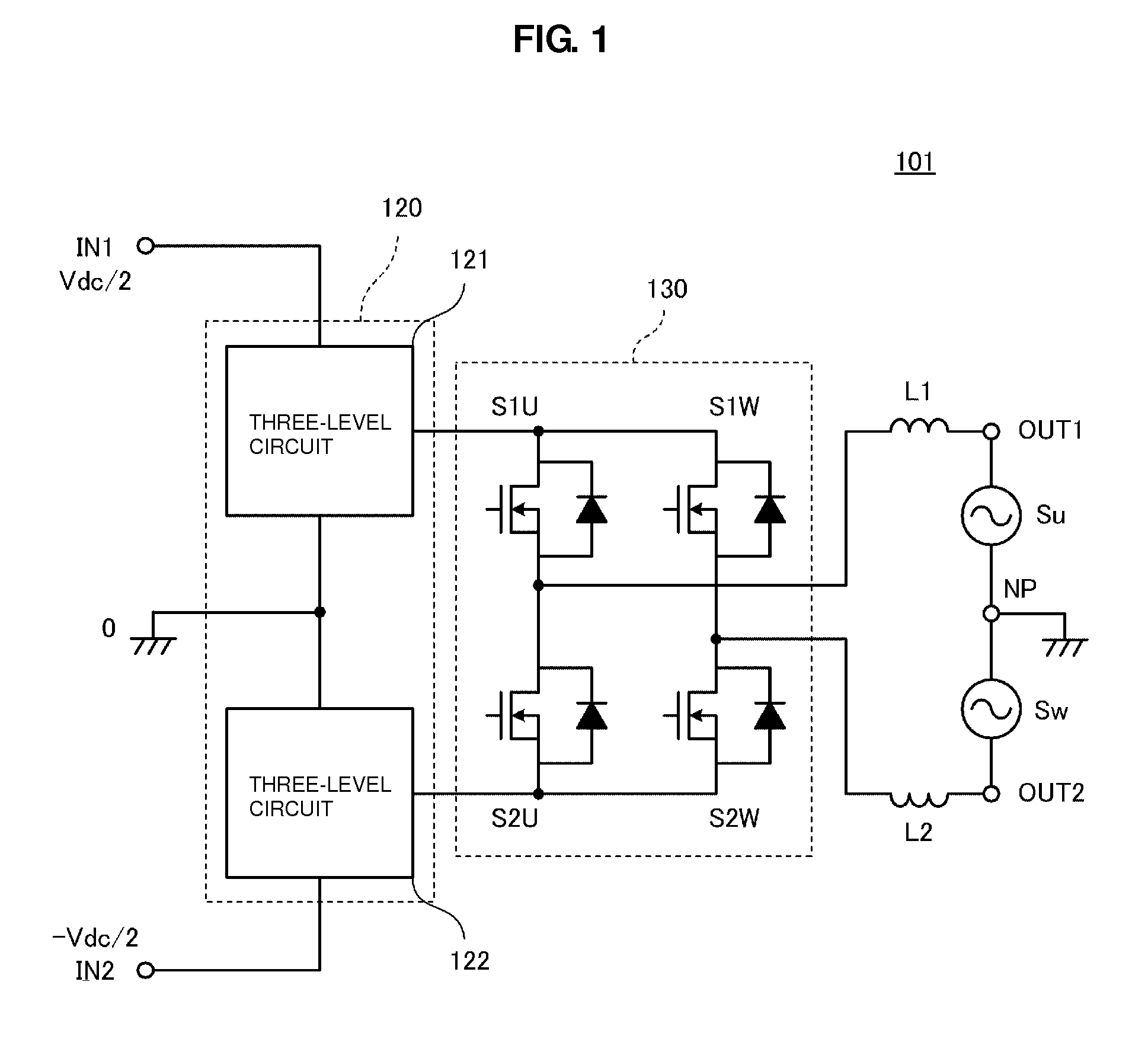
[0042]FIG. 1 is the partially blocked circuit diagram of an inverter device 101 according to a first preferred embodiment of the present invention. The inverter device 101 preferably includes a first input end IN1 and a second input end IN2, into which direct-current power supply voltages are input, and a first output end OUT1 and a second output end OUT2, from which alternating-current voltages are output. Direct-current voltages generated due to, for example, a solar power generation panel are applied to the first input end IN1 and the second input end IN2. In FIG. 1, Su and Sw indicate a single-phase three-wire system having a U-phase and a W-phase. An alternating-current voltage whose effective voltage preferably is about 100 V, for example, is applied between the first output end OUT1 and a neutral point NP, an alternating-current voltage whose effective voltage preferably is about 100 V, for example, is applied between the neutral point NP and the second output end OUT2, and a...

second preferred embodiment

[0070]In the first preferred embodiment, in particular as illustrated in FIGS. 13A to 13D and FIGS. 14A to 14D, an example has been illustrated where the switch elements S1 to S4 in the first three-level circuit 121 and the switch elements S5 to S8 in the second three-level circuit 122 are preferably symmetrically coordinated with each other and are driven. However, the present invention is not limited to a configuration where driving is performed in such a way. In a second preferred embodiment, an example will be illustrated where the switch elements S1 to S4 in the first three-level circuit 121 and the switch elements S5 to S8 in the second three-level circuit 122 preferably are independently driven.

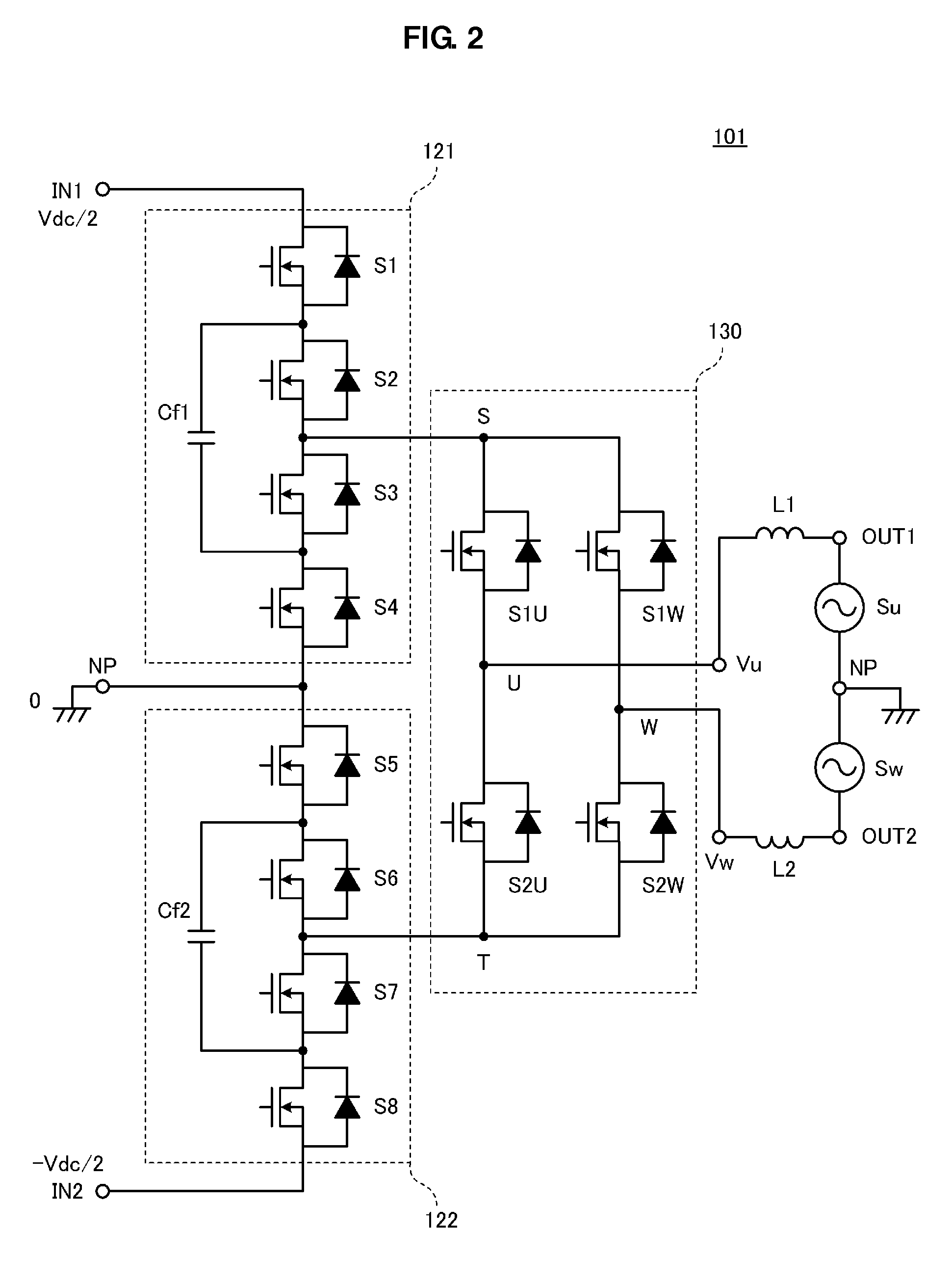
[0071]The circuit configuration of an inverter device in the second preferred embodiment preferably is the same or substantially the same as that illustrated in FIG. 1 and FIG. 2. Accordingly, the symbols illustrated in FIG. 1 and FIG. 2 will be referred to in the following description...

third preferred embodiment

[0074]While, in the first and second preferred embodiments, examples have been illustrated where the positive voltage and the negative voltage preferably are applied to the first input end IN1 and the second input end IN2, respectively, the present invention is not limited to a configuration where two voltages whose polarities are positive and negative are input. In a third preferred embodiment, an example will be illustrated where a direct-current voltage having a single polarity is input.

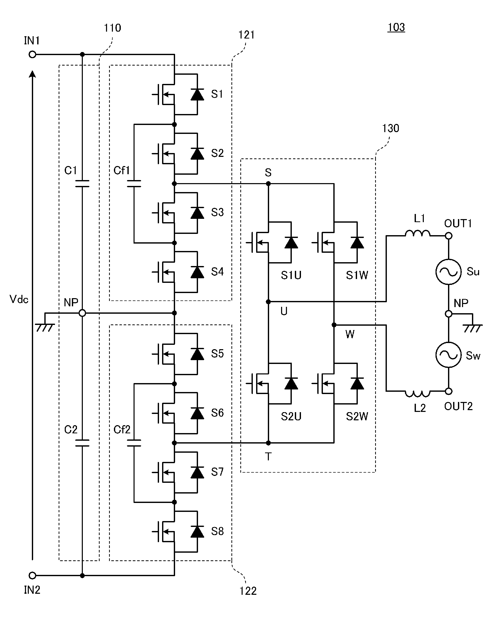
[0075]FIG. 23 is the circuit diagram of an inverter device 103 according to the third preferred embodiment. This inverter device 103 includes a first input end IN1 and a second input end IN2, into which a direct-current power supply voltage is input, and a first output end OUT1 and a second output end OUT2, from which alternating-current voltages are output. A direct-current voltage generated by, for example, a solar power generation panel, is applied between the first input end IN1 and the second...


PUM


Abstract

In an inverter device, a first three-level circuit includes first to fourth preceding-stage switch elements connected in series between a first input end and a ground and a first charging and discharging capacitor. A second three-level circuit includes fifth to eighth preceding-stage switch elements connected in series between a second input end and the ground and a second charging and discharging capacitor. The first and second two three-level circuits define a five-level circuit that is subjected to switching with the carrier frequency of PWM modulation. The output polarity of a subsequent-stage bridge clamping circuit is inverted between the anterior half cycle and the posterior half cycle of a power supply frequency.

Description

BACKGROUND OF THE INVENTION[0001]1. Field of the Invention[0002]The present invention relates to a DC / AC inverter device, and, in particular, relates to an inverter device including a multilevel circuit.[0003]2. Description of the Related Art[0004]In recent years, for example, solar power generation systems have prevailed, and, from a viewpoint of the high efficiency thereof, non-insulated types have entered the mainstream of power-system-interconnected inverters (hereinafter, a power system is simply referred to as a “system”). So as to generate a substantially sinusoidal voltage in an insulated type inverter (so as to inject a substantially sinusoidal current into a system), an inverter device has been disclosed, for example, in Japanese Unexamined Patent Application Publication No. 2006-223009, the inverter device being equipped with a multilevel circuit outputting a plurality of voltages whose number is greater than or equal to three.[0005]In FIG. 1 in Japanese Unexamined Patent...

Claims


Application Information

Patent Timeline
Patent Type & Authority Patents(United States)
IPC IPC(8): H02M7/5387H02M7/487
CPCH02M7/5387H02M7/487H02M7/483H02M1/007H02M1/0095H02M7/4837
Inventor ITOH, JUNICHINOGE, YUICHI
Owner MURATA MFG CO LTD
Why Eureka
Try Eureka