Inductor

a technology of inductors and cores, applied in the field of magnetic components, can solve the problems of affecting the use of low-profile perforated plates for magnetic core substrates, affecting the performance of inductors, so as to prevent the saturation of cores and reduce the volume of materials

Inactive Publication Date: 2007-01-04
THE BOEING CO
View PDF5 Cites 10 Cited by
  • Summary
  • Abstract
  • Description
  • Claims
  • Application Information

AI Technical Summary

Benefits of technology

[0013] It is another feature of this invention to minimize the ma

Problems solved by technology

Such structures are typically bulky and their physical dimensions often define the minimum size requirement of associated devices or subsystems.
The use of low-profile perforated plates for magnetic core substrates was hampered, in part, due to inaccuracies in modeling the inductance of s

Method used


Image

  • Inductor
  • Inductor
  • Inductor

Examples


Embodiment Construction

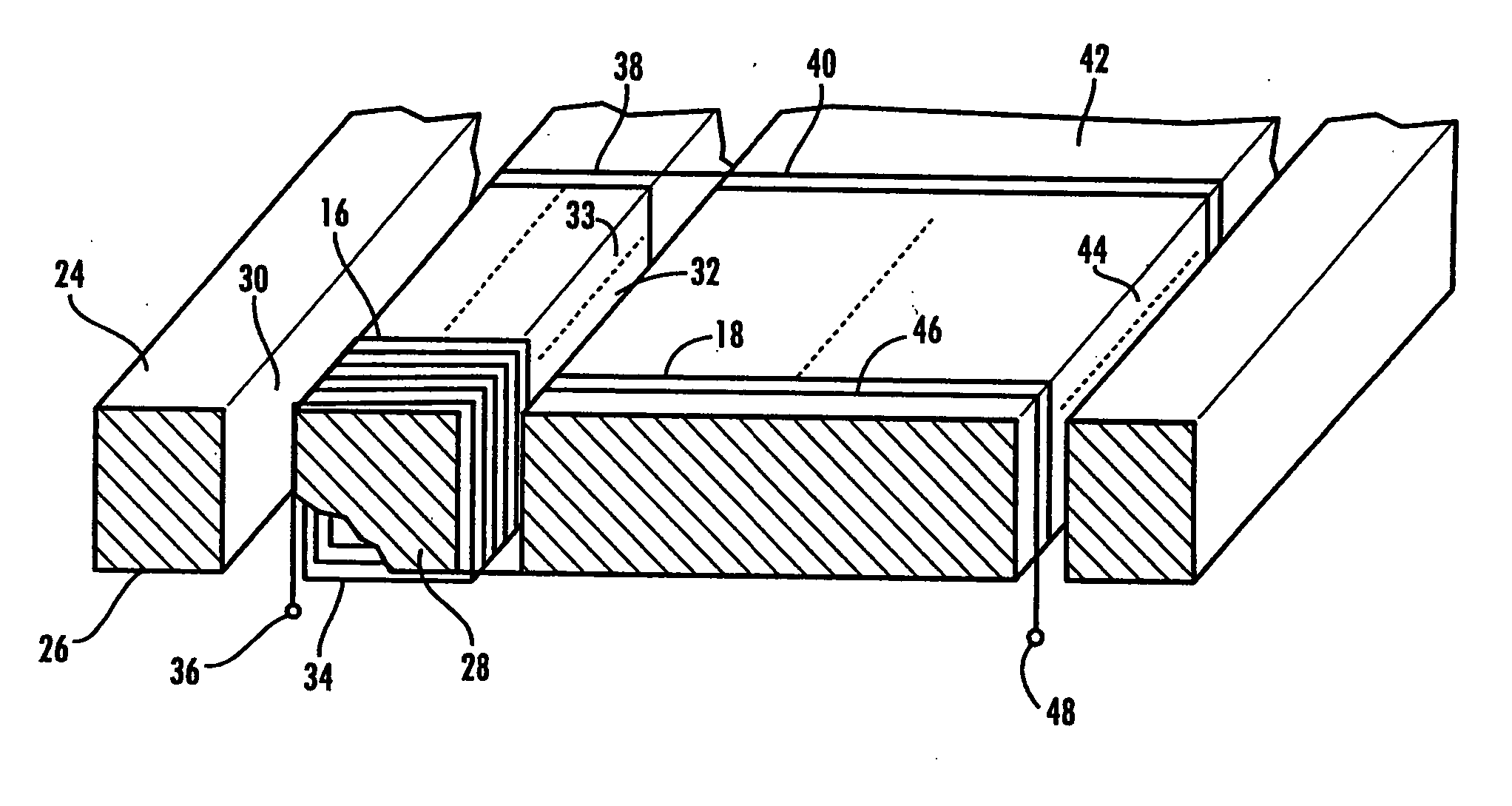
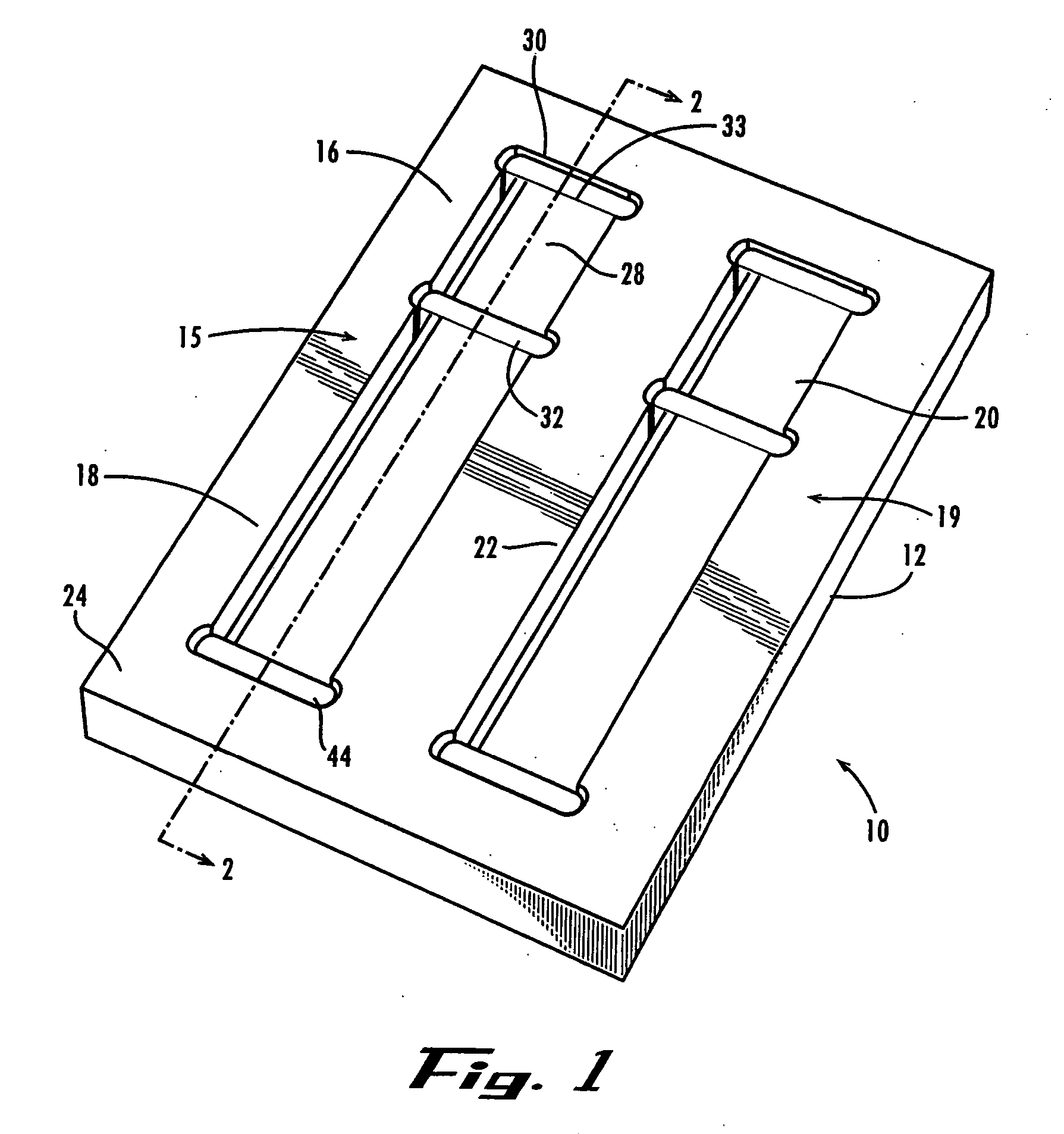
[0021] Turning first to FIG. 1, there is shown generally at 10 a flat-plate inductor according to a disclosed embodiment of the present invention. The inductor 10 comprises a plurality of windings described below in further detail, disposed on a magnetic substrate 12 in the form of a flat plate. The substrate 12 is comprised of a manganese-zinc ferrite composition, in a disclosed embodiment of the inductor. The several windings are disposed on the substrate by techniques known in the art, such as copper plating onto the substrate or copper wires deposited in accordance with photoresistive deposition techniques. In the case of multiple-layer windings of the inductor 10, individual conductor layers are insulated from each other in accordance with known photoresistive deposition techniques, thereby providing a plurality of winding layers on the substrate 12.

[0022] The inductor 10 of the disclosed embodiment contains two set of windings. The first set 15 of windings comprises a first w...


PUM


Abstract

An inductor comprising one or more windings disposed on opposed first and second surfaces of a flat-plate substrate. The windings are applied to the substrate by plating or photoresistive deposition techniques, with through-holes through the plate accommodating the windings from opposed surfaces. Windings of more than one layer are obtainable with insulation between adjacent layers. The resulting inductor is usable, for example, as a component of an EMI filter in a power converter circuit.

Description

FIELD OF THE INVENTION [0001] The present invention relates in general to magnetic components, and relates more particularly to inductors having magnetic cores for use in electronic applications such as power conditioning circuits and DC-DC converters. BACKGROUND OF THE INVENTION [0002] Numerous modern-day electrical circuits utilize magnetic core components in accomplishing desired objectives. Audio and alternating current (AC) transformers and inductors typically include iron, powdered iron, or ferrite magnetic substrates. While the precise composition of such substrates varies with respect to design goals, common form structures take the shape of rods, toroids, or pot cores having single or multiple winding coils integral thereto. The windings in conjunction with the magnetic substrate define the operating parameters of the device. Such structures are typically bulky and their physical dimensions often define the minimum size requirement of associated devices or subsystems. [0003...

Claims


Application Information

Patent Timeline
IPC IPC(8): H01F5/00
CPCH01F17/0006H01F2017/065H01F37/00
Inventor BRANDT, RANDY L.TURNER, H. BRUCE
Owner THE BOEING CO
Why Eureka
Try Eureka