Friction welding process

a technology of friction welding and welding process, which is applied in the direction of mechanical equipment, manufacturing tools, turbines, etc., can solve the problems of compromising weld integrity, compromising optimum conditions, and compromising weld integrity

Inactive Publication Date: 2019-06-06
ROLLS ROYCE PLC
View PDF18 Cites 0 Cited by
  • Summary
  • Abstract
  • Description
  • Claims
  • Application Information

AI Technical Summary

Benefits of technology

[0017]By providing the weld surface with the combination of first and second pyramidal surfaces, and third and fourth pyramidal surfaces, the workpiece can be subjected to an LFW process and the resulting welded joint does not have trapped contaminants at a centre region of the joint, and also the welded joint does not suffer from deformation and detachment at the edges of the joint.
[0066]Keeping the first pyramidal angle and the second pyramidal angle within the range of approximately 6° and 30° provides a balance between ensuring the elimination of surface contaminants from the weld zone, and minimising the volume of material that must be ejected from the joint as flash during the weld process.

Problems solved by technology

These retained contaminants may compromise the weld integrity.
This potentially compromises weld integrity by exposing the full weld joint to atmospheric contamination formed at the weld interface during heating, for example by forming hard alpha particles in titanium alloys.
Deformation of the edge of the LFW stub can compromise optimum conditions for the extrusion and ejection of contamination from the weld.
In extreme circumstances, the deformed stub corners may detach, further compromising optimum material flow conditions.
The process of deformation and detachment can expose the weld joint to atmospheric contamination formed at the weld interface during heating and compromise optimum conditions for the extrusion and ejection of contamination from the weld joint.
However, when a pyramidal geometry is used for one of the weld stubs then the problem of deformation and detachment has been shown to occur.
This difference in material characteristics between the first workpiece and the second workpiece will result in an asymmetric upsetting behaviour during the friction welding process between the first workpiece and the second workpiece.
If both the first workpiece and the second workpiece have the same geometry then the resulting friction weld will be asymmetric across the weld interface, for example with a harder workpiece ‘burrowing’ into a softer workpiece and so producing a poor quality welded joint.
There may be design limitations on a lateral width of the first workpiece that prevents the geometry of the first workpiece from including third and fourth pyramidal surfaces.

Method used


Image

  • Friction welding process
  • Friction welding process
  • Friction welding process

Examples


first embodiment

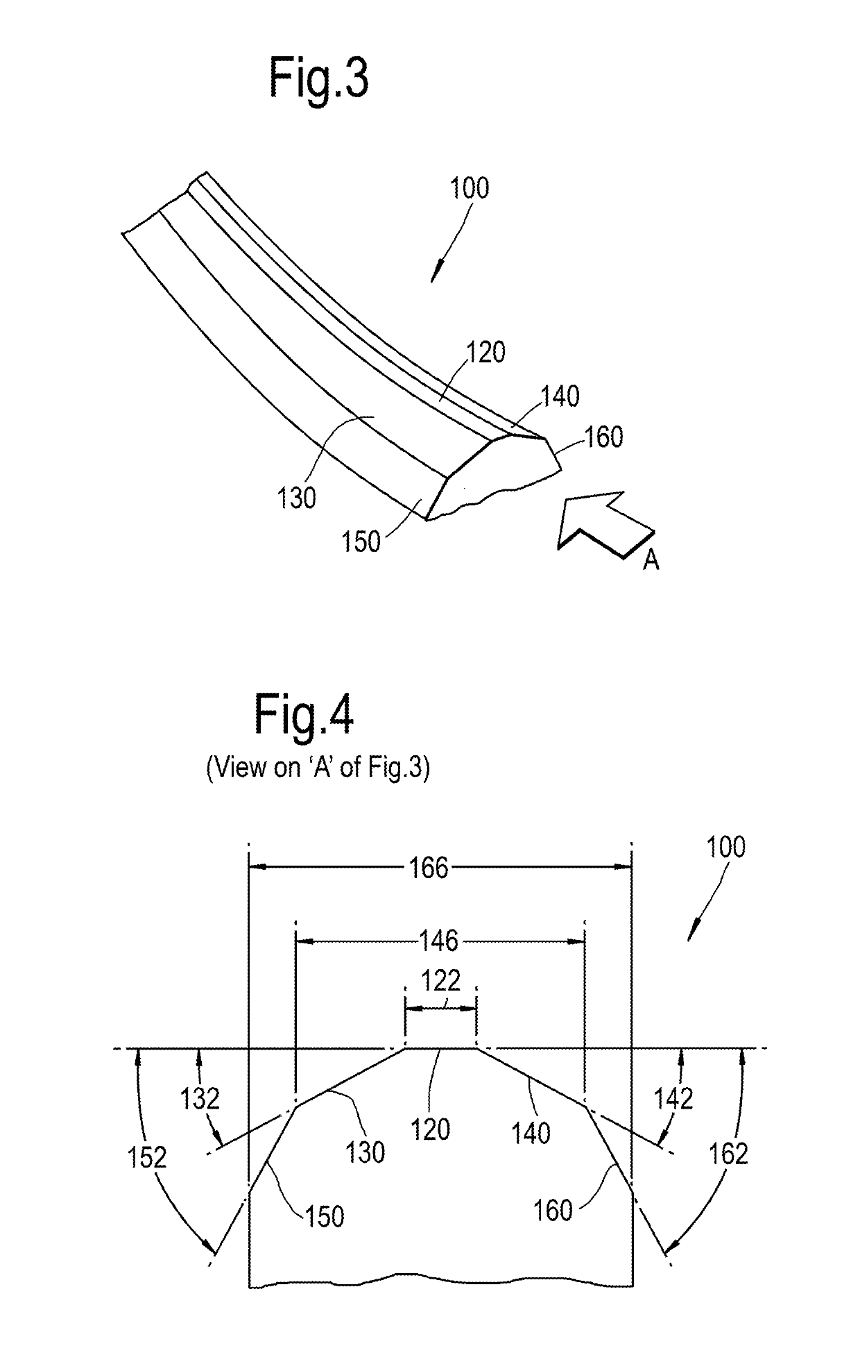
[0092]Referring to FIGS. 3 to 5, a workpiece for use with a friction welding process, according to the disclosure is designated generally by the reference numeral 100.

[0093]The workpiece 100 takes the form of a weld stub 100 and comprises a weld surface 110. The weld surface 110 comprises a central ridge surface 120 extending along the weld surface 110. The central ridge surface 120 extends linearly across a lateral width 122 of the weld surface 110. In the illustrated embodiment the central ridge surface 120 has a lateral width 122 of 4 mm. The central ridge surface 120 is flanked on either side respectively by a first pyramidal surface 130 and a second pyramidal surface 140.

[0094]The first pyramidal surface 130 subtends a first pyramidal angle 132 with the central ridge surface 120. The second pyramidal surface 140 subtends a second pyramidal angle 142 with the central ridge surface 120. The first and second pyramidal surfaces 130,140 together with the central ridge surface 120 to...

second embodiment

[0104]A workpiece according to the disclosure is illustrated in FIG. 8. In this arrangement, the first workpiece 100 is formed from a first material having a first hardness value, and the second workpiece 102 is formed from a second material having a second hardness value, where the first hardness is less than the second hardness. For example, the first workpiece 100 may be formed from a first titanium alloy and the second workpiece 102 may be formed from a second titanium alloy, where the first titanium alloy has a higher hardness than the second titanium alloy.

[0105]Both the first workpiece 100 and the second workpiece 102 have a double pyramidal sectional geometry as outlined above in relation to the first embodiment of the disclosure.

[0106]Each of the first workpiece 100 and the second workpiece 102 comprises a central ridge surface 120A,120B having a lateral width 122A,122B that is flanked on either side respectively by a first pyramidal surface 130A,130B and a second pyramidal...

fourth embodiment

[0120]FIG. 10 illustrates the present disclosure, in which a first workpiece 200 is formed from a first material, and a second workpiece 201 is formed from a second material, with the first and second materials having the same hardness.

[0121]The first workpiece 200 comprises a central ridge surface 220 having a lateral width 222 that is flanked on either side by a first pyramidal surface 230 and a second pyramidal surface 240. The first pyramidal surface 230 subtends a first pyramidal angle 232 with the central ridge surface 220, and the second pyramidal surface 240 subtends a second pyramidal angle 242 with the central ridge surface 220. In this embodiment, each of the first pyramidal angle 232 and the second pyramidal angle 242 is 10°.

[0122]The first pyramidal surface 230 is further flanked by a third pyramidal surface 250 on a distal side of the first pyramidal surface 230 from the central ridge surface 220. The second pyramidal surface 240 is further flanked by a fourth pyramida...


PUM

PropertyMeasurementUnit
pyramidal angleaaaaaaaaaa
flank angleaaaaaaaaaa
widthaaaaaaaaaa

Abstract

A workpiece for use with a friction welding process comprises a weld surface. The weld surface comprises a central ridge surface extending along the weld surface, with the central ridge surface being flanked on either side respectively by a first pyramidal surface and a second pyramidal surface. The first pyramidal surface subtends a first pyramidal angle with the central ridge surface, and the second pyramidal surface subtends a second pyramidal angle with the central ridge surface. The first pyramidal surface is further flanked by a third pyramidal surface, and the second pyramidal surface is further flanked by a fourth pyramidal surface, with the third pyramidal surface subtending a third pyramidal angle with the central ridge surface, and the fourth pyramidal surface subtending a fourth pyramidal angle with the central ridge surface. Each of the third pyramidal angle and the fourth pyramidal angle is less than 90°.

Description

[0001]This application is based upon and claims the benefit of priority from British Patent Application Number 1614566.6 filed 26 Aug. 2016, the entire contents of which are incorporated by reference.FIELD OF THE DISCLOSURE[0002]The present disclosure relates to a friction welding process and particularly, but not exclusively, to a linear friction welding process, together with a weld stub geometry for use with the method.BACKGROUND TO THE DISCLOSURE[0003]Linear friction welding (LFW) is a solid state welding process for joining regular and irregular sections of metallic or non-metallic materials either welded to themselves or each other.[0004]Welds are produced by linear oscillation, at a given frequency, of one part against the other while the parts are pressed together by a forge force applied to the interface.[0005]During the LFW process, the components are locally heated at the contact zone by the friction force resulting from the combination of relative oscillatory motion and ...

Claims


Application Information

Patent Timeline
Patent Type & Authority Applications(United States)
IPC IPC(8): B23K20/12B23K33/00
CPCB23K20/1205B23K20/129B23K20/12B23K33/00B23K2101/001B23K2103/26B23K20/002B23K20/122B23K2103/14
Inventor BRAY, SIMON E.WALPOLE, ANDREW R.WILSON, ROBIN
Owner ROLLS ROYCE PLC
Why Eureka
Try Eureka