Aspirator for manipulating filaments

a technology of filament and aspirator, which is applied in the direction of filament/thread forming, thin material processing, paper and paper, etc., can solve the problems of non-linear control, damaged fibers, waste materials, etc., and achieve the reduction of the overall footprint and weight of the manifold, and the speed of fluid flow. increase or decrease.

Active Publication Date: 2021-11-11
COLUMBIA INSURANCE CO
View PDF24 Cites 0 Cited by
  • Summary
  • Abstract
  • Description
  • Claims
  • Application Information

AI Technical Summary

Benefits of technology

[0013]The fluid metering valve employed in the presently disclosed aspirator is provided with a barrel valve having a passage that extends off-axis along a length of and through the barrel valve. When in a closed orientation, a solid portion of the barrel valve blocks the passage intermediate the two flow channels. Rotation of the barrel valve exposes a portion of the passage intermediate the two flow channels, allowing a metered amount of fluid flow therebetween. The off-axis passage and associated solid portion of the barrel valve enable the thickness of the distribution manifold receiving the valve to be minimized, thereby reducing the overall footprint and weight of the manifold.
[0014]Beneficially, the passage is formed with a square, rectangular, or rounded rectangular cross-section. Such a configuration enables a linear or near linear relationship between change in fluid flow volume through the passage and change in angular position of the barrel valve relative to the distribution manifold. This linearity provides a more predictable response to valve manipulation. In addition, such a configuration enables the valve to change from fully closed to fully open in less than one-hundred twenty degrees of barrel valve rotation and in another embodiment, ninety degrees or less, allowing for a faster rate of fluid flow increase or decrease.
[0015]A further advantage enabled by the presently disclosed fluid metering valve is that the volume of material in the barrel valve can be minimized, thereby contributing to weight and size reduction.

Problems solved by technology

However, known aspirator guns have suffered from non-linear control over the flow of air used to attract and draw extruded fibers, thus leading to unpredictable efforts at manipulating such fibers.
This often leads to damaged fibers and wasted materials.
Most polymer filaments are very abrasive as they flow through aspirators at typical speeds.
Other prior art aspirators utilize hardened materials that are more resistant to wear, but are thus heavy and harder to manipulate precisely.

Method used


Image

  • Aspirator for manipulating filaments
  • Aspirator for manipulating filaments
  • Aspirator for manipulating filaments

Examples


Embodiment Construction

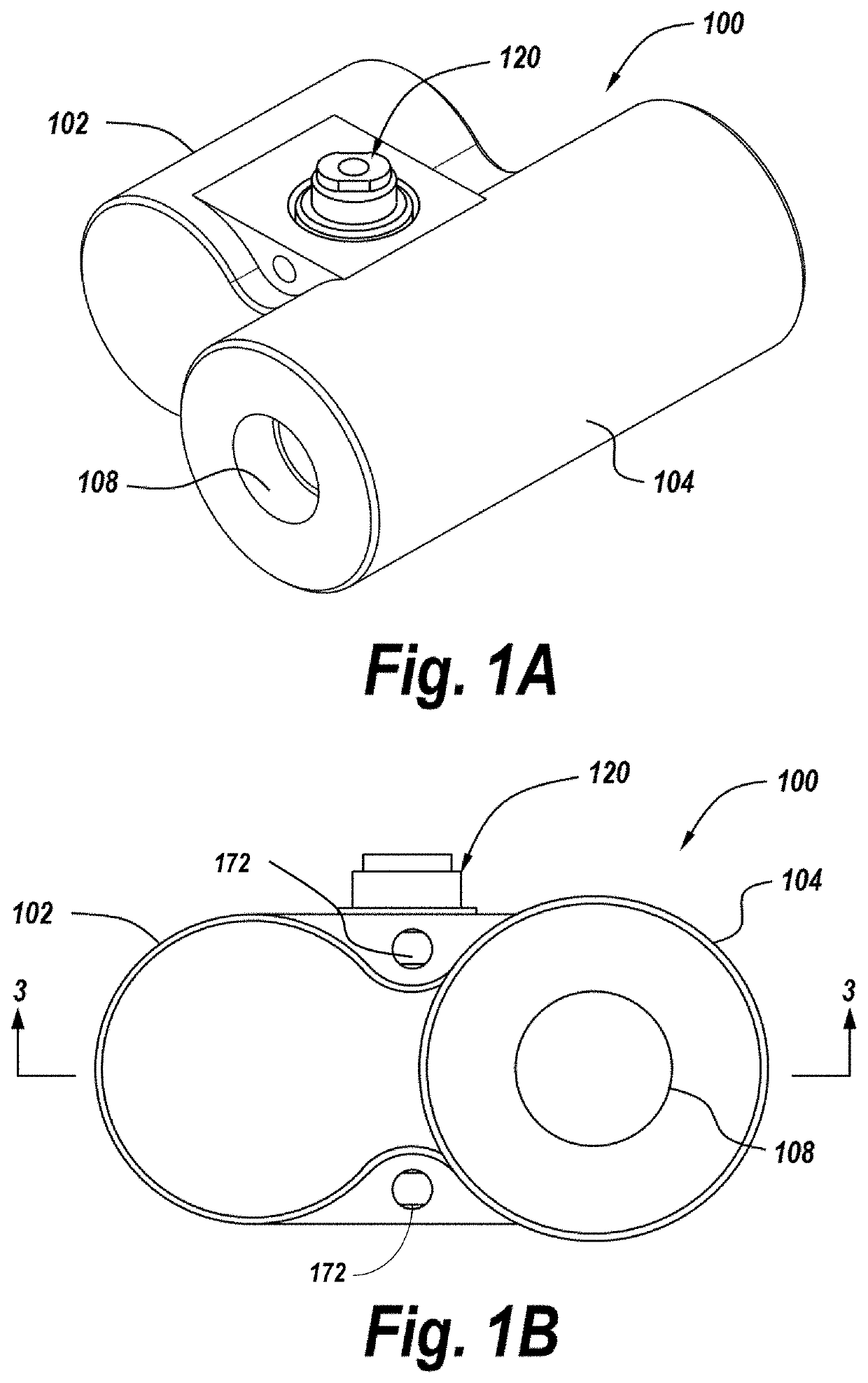
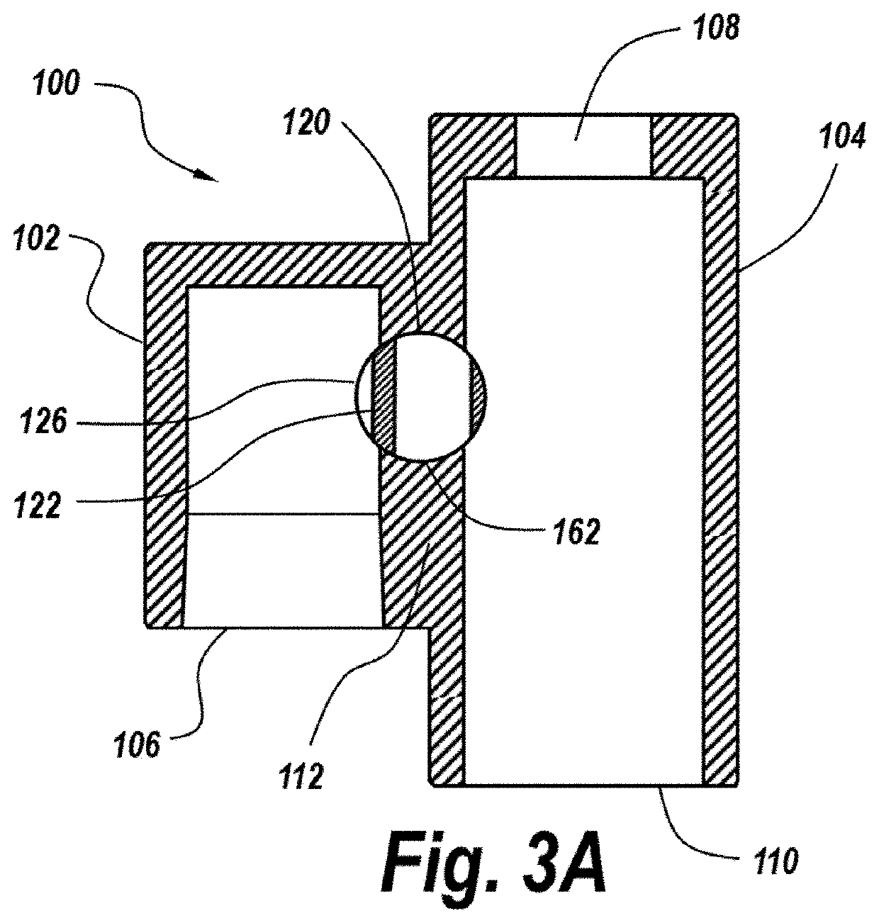
[0033]FIGS. 1A and 1B show a particular embodiment of a distribution manifold 100 having a barrel valve assembly 120 disposed therein according to the present disclosure. The illustrated manifold includes first and second mutually parallel flow channels 102, 104, the flow channels being in selective mutual communication via the valve assembly. The manifold is also visible in a horizontal section views in FIGS. 3A and 3B.

[0034]In the illustrated embodiment, the first flow channel 102 terminates within the manifold, opposite an open end 106, while the second flow channel 104 has dual open ends 108, 110, though the presently disclosed valve assembly 120 is operable in association with other manifold embodiments as well. Each flow channel open end can be provided with suitable features to facilitate the selective coupling of fluid-conveying members, such as hoses, tubes or pipes, as will be discussed below with regard to an aspirator assembly of the present disclosure. These features ca...


PUM

PropertyMeasurementUnit
central angleaaaaaaaaaa
internal diameteraaaaaaaaaa
angleaaaaaaaaaa

Abstract

An aspirator provides linear control over air flow for manipulation of extruded fibers. A distribution manifold has a barrel valve between first and second flow channels, enabling precise, linear control over air flowing from a charge conduit to a pressure chamber surrounding a discharge pipe. Plural orifices in the discharge pipe connect the pressure chamber to the interior thereof, which is configured as a Venturi tube. Discharge pipe surfaces that can contact filaments therein are of hardened material while non-contact surfaces are of lighter materials.

Description

CROSS-REFERENCE TO RELATED APPLICATION[0001]This application claims the benefit of priority U.S. Provisional Application No. 63 / 020,509, filed on May 5, 2020, the entirety of which is incorporated herein by reference.BACKGROUND[0002]The production of nonwoven webs of fibrous elements, such as polymer filaments requires the use of tools for manipulating the filaments without tangling them. For example, when polymer filaments are extruded from spinnerets, it is necessary to collect the cooled filaments and direct them to further processing equipment, including Godet rollers and winding spools. Aspirator guns have typically been used for this purpose.[0003]However, known aspirator guns have suffered from non-linear control over the flow of air used to attract and draw extruded fibers, thus leading to unpredictable efforts at manipulating such fibers. This often leads to damaged fibers and wasted materials.[0004]Most polymer filaments are very abrasive as they flow through aspirators at...

Claims


Application Information

Patent Timeline
Patent Type & Authority Applications(United States)
IPC IPC(8): D02J1/08D02G1/16
CPCD02J1/08D02G1/16D01D5/00B65H51/16
Inventor TANKERSLEY, ADAMGUZOWSKI, JESSE
Owner COLUMBIA INSURANCE CO
Why Eureka
Try Eureka