
Method and system for frequency hopping radio communication

a frequency hopping and radio communication technology, applied in the direction of orthogonal multiplex, connection management, synchronisation arrangement, etc., can solve the problems of increased production cost, difficult operation, and more difficult to realize a frequency-stable and low phase noise hopping synthesizer

Inactive Publication Date: 2005-11-10
NAT INST OF INFORMATION & COMM TECH
View PDF8 Cites 8 Cited by
  • Summary
  • Abstract
  • Description
  • Claims
  • Application Information

AI Technical Summary

Benefits of technology

[0006] The present invention has been developed to solve the above-mentioned problems, and aims at configuring a wireless system in a frequency hopping system free of the effect of a local oscillator for a frequency conversion or the unstable frequency of a hopping synthesizer.
[0007] The present invention also aims at realizing a small and low-cost and system capable of applying without a highly stable local oscillator or hopping synthesizer a frequency hopping system in a very high frequency area such as a milliwave band in which the frequency hopping system has conventionally been very difficult.

Problems solved by technology

However, as the frequency becomes higher (for example, a milliwave band of 30 GHz or more), it is more difficult to realize a frequency-stable and low phase noise hopping synthesizer, and the production cost rises.
However, it is very hard to operate in, for example, a high frequency such as a milliwave band a hopping synthesizer capable of synchronize a frequency with high precision, and it is also very difficult to immediately take action against an occurrence of a large frequency offset or synchronously supplement it, thereby requiring an expensive system stabilizing mechanism.

Method used


Image

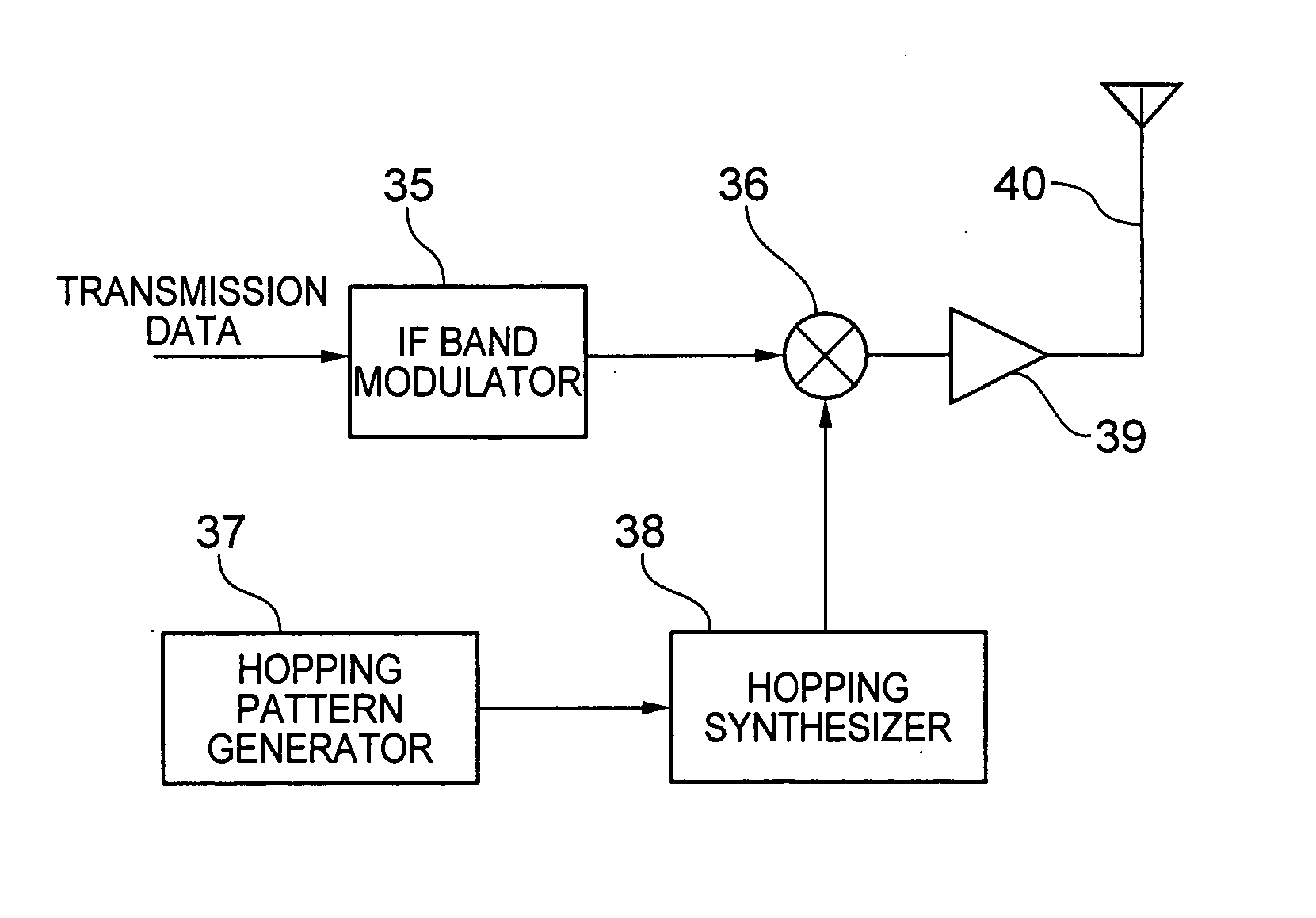
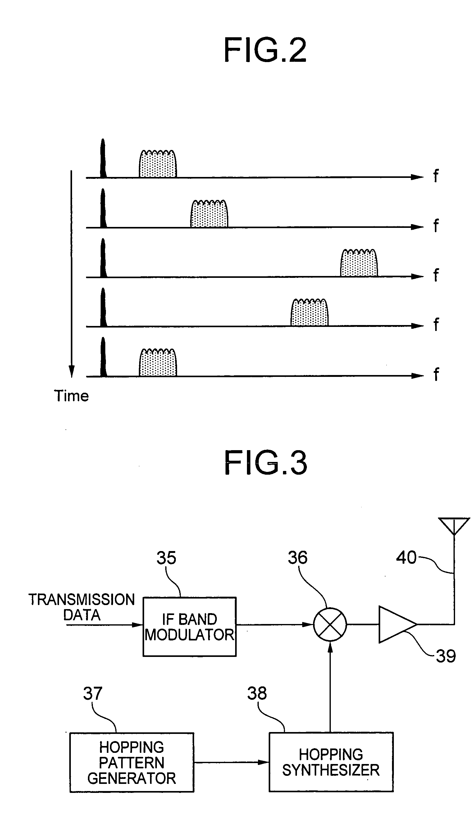
  • Method and system for frequency hopping radio communication
  • Method and system for frequency hopping radio communication
  • Method and system for frequency hopping radio communication

Examples


first embodiment

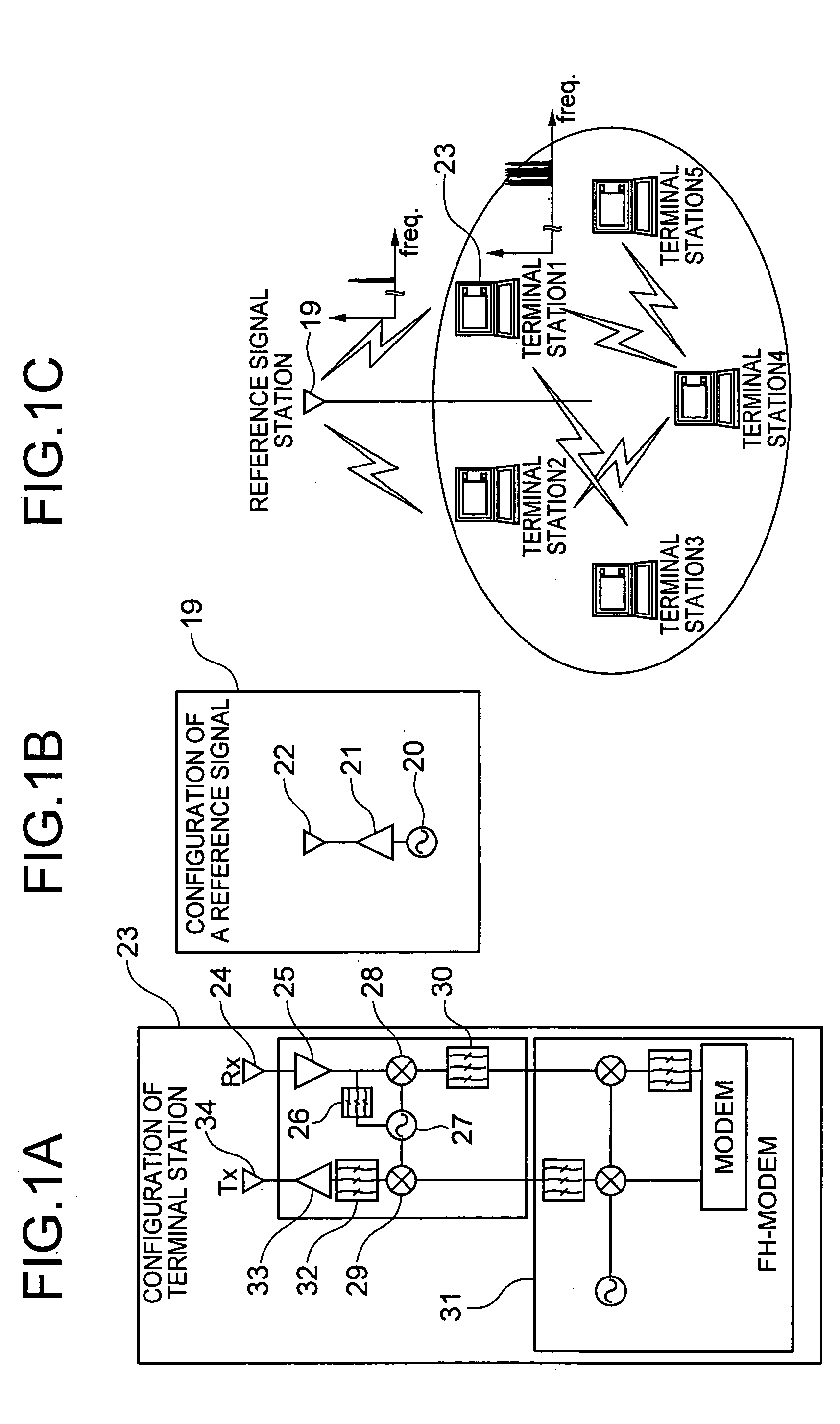
[0017]FIG. 1 shows the configuration of the wireless communication system according to the first embodiment of the present invention. FIG. 2 shows the transition os a signal spectrum transmitted and received by each station. As shown in FIG. 1C, the system comprises one reference signal station 19 and a plurality of terminal stations 23. As shown in FIG. 1B, the reference signal station 19 amplifies the reference local oscillation signal generated by a reference station local oscillator 20 using an amplifier 21, and then transmits the signal from an antenna 22. As shown in FIG. 1A, each terminal station 23 receives it using a receiving antenna 24. The received signal is amplified by an amplifier 25, a part of the resultant signal is branched, a band pass filter 26 removes an unnecessary wave, and the resultant signal is input to the synchronous oscillator or an amplifier 27. As a result, a local oscillation signal synchronous with the reference local oscillation signal output by the...

second embodiment

[0023]FIGS. 3 and 4 show the configuration of a transmitter and the configuration of a receiver of the wireless communication system according to the second embodiment of the present invention. FIG. 5 shows the transition of the spectrum of a signal transmitted and received between terminals. The present invention can be applied to the communications between a plurality of wireless terminals, and each wireless terminal comprises a transmitting unit as shown in FIG. 3 and a receiving unit as shown in FIG. 4, thereby performing bi-directional communications.

[0024] The transmitter shown in FIG. 3 generates an IF band modulation signal using an IF band modulator 35 and inputs an FH signal obtained by a hopping synthesizer 38 controlled by a hopping pattern generator 37 and the IF band modulation signal to a mixer 36, thus obtains a frequency hopping radio signal. The output includes an output signal of a hopping synthesizer used as a local oscillation signal in addition to the radio si...


PUM


Abstract

A transmitter shown in FIG. 3 inputs to a mixer 36 an IF band modulation signal generated from transmission data and a frequency hopping signal obtained by a hopping synthesizer 38 controlled by a hopping pattern generator 37, thereby obtaining a frequency hopping radio signal to be transmitted. In a receiver shown in FIG. 4, a received signal is amplified and an unnecessary wave is removed from the signal, and the resultant signal is input to a mixer 44. The mixer 44 receives an output signal of a hopping synthesizer 47 controlled by a signal obtained by adding a fixed frequency offset signal to the hopping pattern generator 45. A signal downconverted to a first IF band without frequency hopping corresponding to the offset signal with a radio frequency band signal maintaining the relative spectrum relationship appears in the output of the mixer 44. An unnecessary wave of the signal is removed, a square unit 49 performs square detection, and a modulation signal in the intermediate frequency band used by the source is regenerated. The obtained IF band signal is modulated, thereby receiving desired data.

Description

TECHNICAL FIELD [0001] The present invention relates to a frequency hopping wireless communication method and system for performing wireless communication to which a frequency hopping system is applied in an area of a high frequency such as a milliwave band, etc. BACKGROUND ART [0002] When a wireless communication system for use in a frequency band requiring no license, it is effective to implement a frequency hopping system as means for avoiding or sufficiently suppressing the effect of a narrow-band interference. [0003]FIGS. 6 and 7 show the configurations of the transmitter and the receiver of a wireless communication system when a common frequency hopping system is used. The transmitter obtains a frequency hopping radio modulation signal by inputting to a mixer 4 a signal obtained from an intermediate frequency (IF) band modulator 1 for receiving transmission data and an output of a hopping synthesizer 3 controlled by a signal from a hopping pattern generator 2. An unnecessary w...

Claims


Application Information

Patent Timeline
IPC IPC(8): H04B1/713H04B1/7136H04J11/00H04W56/00H04W72/04H04W76/02
CPCH04B1/7156H04B1/713
Inventor SHOJI, YOZOOGAWA, HIROYO
Owner NAT INST OF INFORMATION & COMM TECH
Learn More