Power supply device for charge/discharge device, and charge/discharge device

US20090237028A1Active Publication Date: 2009-09-24SANSHA ELECTRIC MFG

Image

  • Power supply device for charge/discharge device, and charge/discharge device
  • Power supply device for charge/discharge device, and charge/discharge device
  • Power supply device for charge/discharge device, and charge/discharge device

Examples


Embodiment Construction

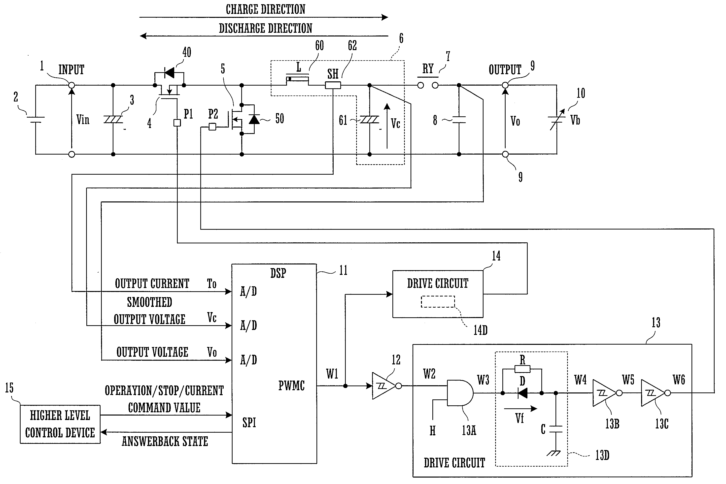
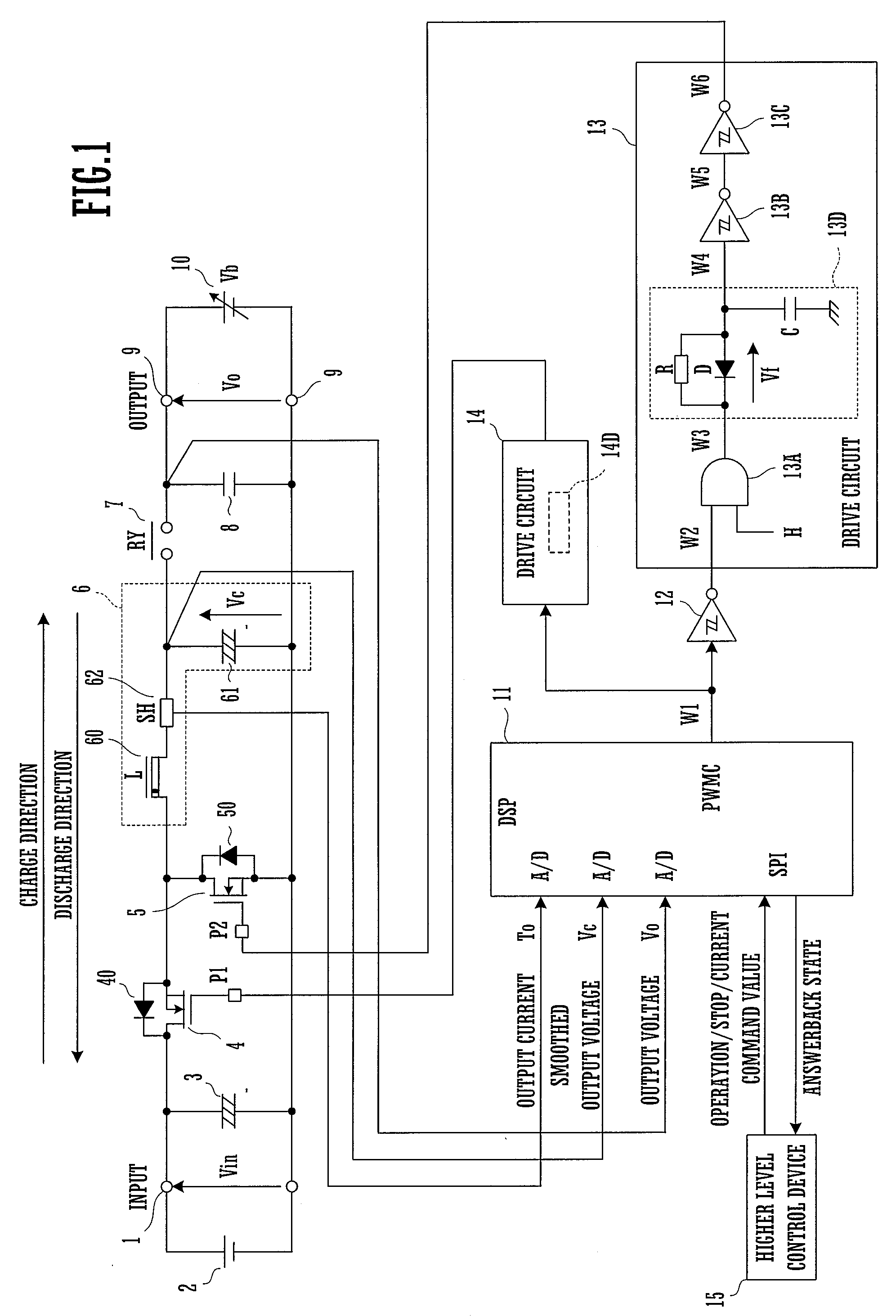
[0035]FIG. 1 is a block diagram of a charge / discharge device which is an embodiment of the present invention.

[0036]This charge / discharge device is used as a test device for testing the characteristics of a secondary battery by repeatedly charging and discharging that secondary battery.

[0037]A DC power supply unit 2 is connected to input terminals 1. Provided that its output voltage is a DC voltage, this DC power supply unit 2 may comprise a battery or an AC-DC converter or the like.

[0038]To the input terminals 1 there are connected in parallel a first smoothing capacitor 3 and a series circuit comprising a first switching element 4 and a second switching element 5. By “connected in parallel” is meant being directly or indirectly electrically connected in parallel between the input terminals 1, and includes both being connected in parallel without the interposition of any element or circuit, and being connected in parallel via some element or circuit.

[0039]Each of the first switching...


PUM


Abstract

This power supply device includes a series circuit of a first switching element and a second switching element connected in parallel with a DC power supply unit, and a smoothing filter circuit which includes a series circuit of an inductor and a smoothing capacitor connected in parallel with the second switching element. The power supply device also includes a control unit and a drive circuit for generating first and second PWM pulses by respectively driving the first and second switching elements ON and OFF, and for creating a dead time between those switching pulse signals. And this control unit changes the frequency of the switching pulse signal according to the pulse width of either the first PWM pulses or the second PWM pulses.

Description

CROSS REFERENCE[0001]This Nonprovisional application claims priority under 35 U.S.C. §119(a) on Patent Application No. 2008-070591 filed in Japan on Mar. 19, 2008, the entire contents of which are hereby incorporated by reference.BACKGROUND OF THE INVENTION[0002]The present invention relates to a charge / discharge device, and to a power supply device for a charge / discharge device or the like. In particular, it relates to a power supply device, to the output terminals of which a secondary battery is connected, and which is adapted for performing testing of the battery characteristics (the electrical discharge characteristic and the capacity and so on) of this secondary battery by repeatedly performing charge and discharge thereof.[0003]In the testing of a secondary battery such as a lithium ion battery or the like, normally, testing is performed by repeatedly charging and discharging the secondary battery by connecting it as a test subject to output terminals. For example control may ...

Claims


Application Information

Patent Timeline
24 Sep 2009
Publication
US20090237028A1
IPC
H02J7/00; G05F1/10; H02M3/155
CPC
H02M3/1582; H02M1/08
Inventors
YORINOBU, MASANORI; OKAMOTO, SHIGERU