Compound eye-camera module

a camera module and compound technology, applied in the field of small-scale thin camera modules, can solve the problems of limited light wavelengths to which individual lenses are devoted, and unnecessarily large number of reflected images, so as to prevent unwanted incident light from being reflected small and low-cost

Active Publication Date: 2011-01-04
PANASONIC INTELLECTUAL PROPERTY CORP OF AMERICA
View PDF12 Cites 10 Cited by
  • Summary
  • Abstract
  • Description
  • Claims
  • Application Information

AI Technical Summary

Benefits of technology

The present invention solves the conventional problems described above, and the object of the present invention is to provide a small and low-cost compound-eye camera module while preventing unwanted incident light from being reflected in an imaging region.

Problems solved by technology

Thus, the wavelengths of light to which the individual lenses are devoted are limited.
Therefore, although a light beam with large incident angle whose image forming position is displaced greatly from the imaging region does not enter the imaging region directly, it is reflected by the light-shielding wall 113a, leading to a problem that a reflected image is formed on a captured picture in the imaging region.
On the other hand, when the imaging region is set so that the reflected image is not formed in the imaging region, there is no alternative but to use an imaging device with the unnecessarily large number of pixels or to use a smaller imaging region.
In this case, there have been problems of increased cost and lowered performance.

Method used


Image

  • Compound eye-camera module
  • Compound eye-camera module
  • Compound eye-camera module

Examples


embodiment 1

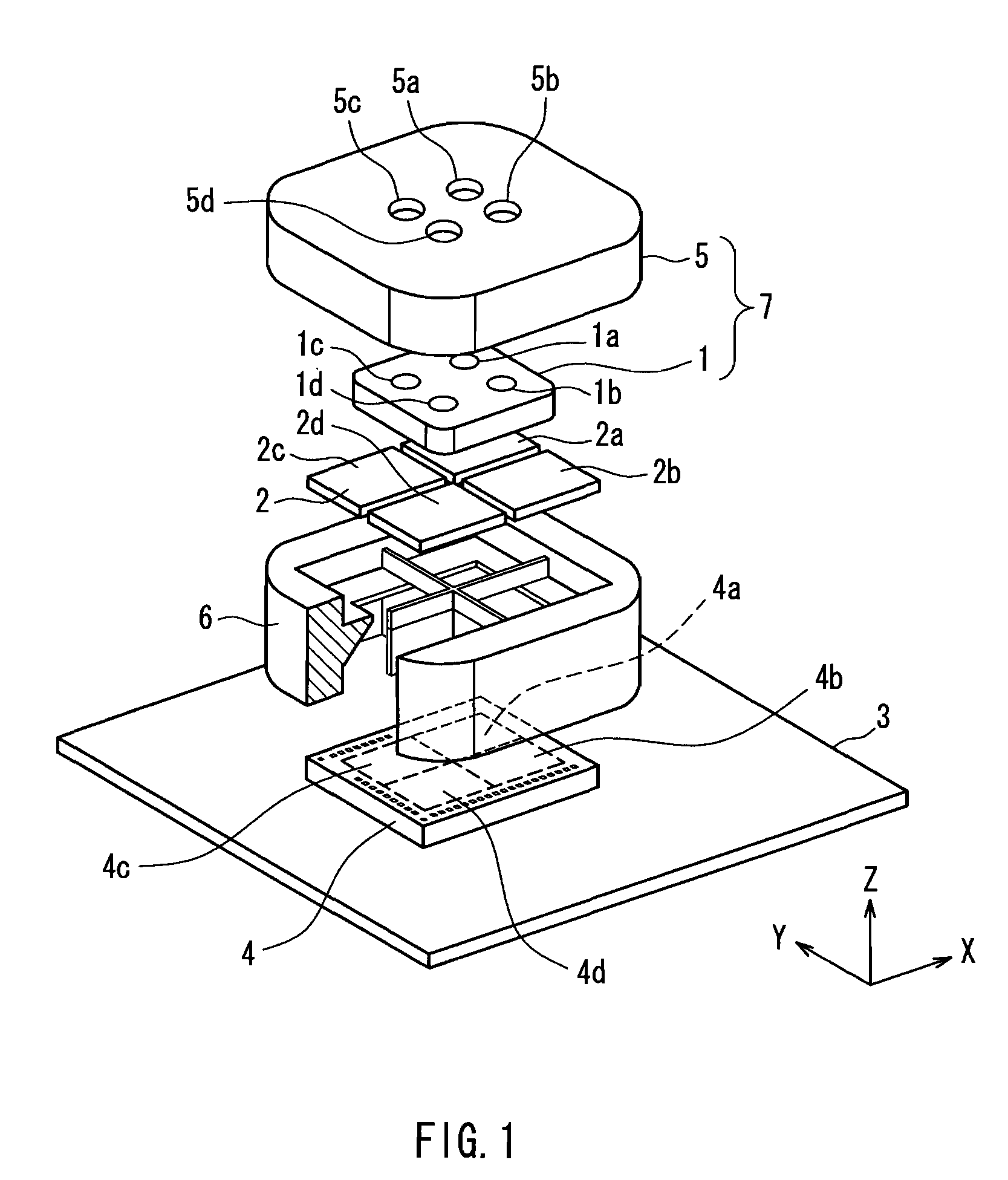
FIG. 1 is an exploded perspective view showing a compound-eye camera module according to Embodiment 1 of the present invention. In FIG. 1, numeral 1 denotes a lens array, numeral 2 denotes an optical filter array, numeral 3 denotes a substrate, numeral 4 denotes an imaging device, numeral 5 denotes an upper barrel, and numeral 6 denotes a light-shielding block.

For the convenience of description, an XYZ rectangular coordinate system as shown in the figure is set. The Z axis is an axis that passes through a substantial center of an effective pixel region of the imaging device 4 and is perpendicular to the effective pixel region. The Z-axis direction also is an optical axis direction of each of lenses forming the lens array 1. The X axis is an axis that is perpendicular to the Z axis and parallel with light-shielding walls 61a and 61c, which will be described later, of the light-shielding block 6. The Y axis is an axis that is perpendicular to the Z axis and parallel with light-shieldi...

embodiment 2

In the following, Embodiment 2 of the present invention will be described, with reference to FIGS. 5A and 5B. FIG. 5A shows light rays in a compound-eye camera module according to Embodiment 2 of the present invention. Similarly to FIG. 3, this figure corresponds to the figure showing light rays at a cross-section along the YZ plane passing through the lenses 1a and 1b of the camera module of FIG. 1. FIG. 5B is an enlarged view showing a portion of a light-shielding wall in FIG. 5A.

The present embodiment has a similar configuration to Embodiment 1 except for an inclination angle of the inclined surfaces of the light-shielding wall. Thus, individual structures are assigned the same reference numerals as those in Embodiment 1, and the redundant description thereof will be omitted.

In FIGS. 5A and 5B, similarly to Embodiment 1, the light-shielding walls 61a to 61d are provided perpendicularly in the Z direction that is substantially perpendicular to the imaging plane. The configuration ...

embodiment 3

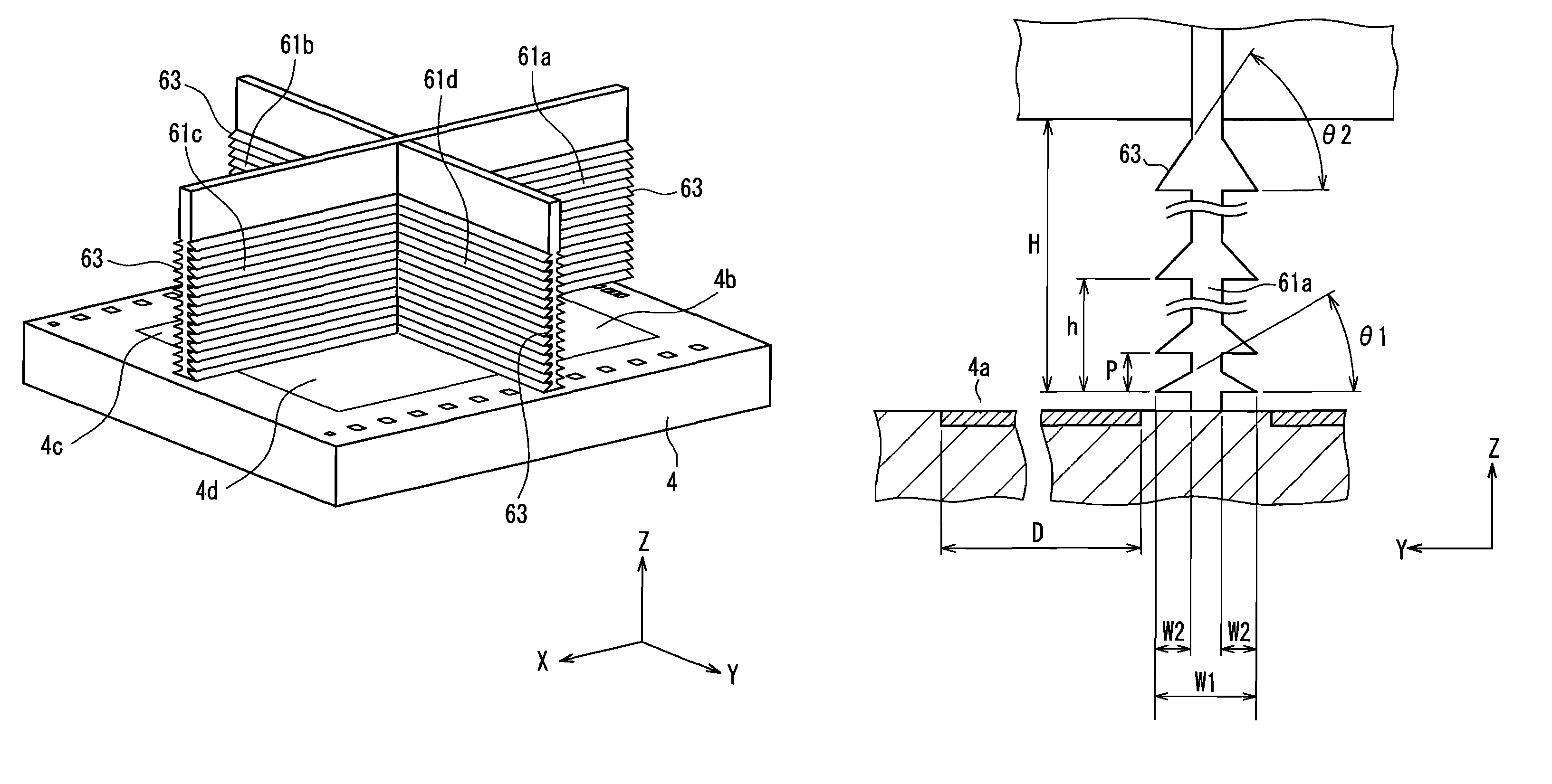
In the following, Embodiment 3 of the present invention will be described, with reference to FIG. 6. FIG. 6 is a perspective view specifically showing an imaging device and light-shielding walls in a compound-eye camera module according to Embodiment 3. This figure corresponds to FIG. 4 in Embodiment 1. The present embodiment has a similar configuration to Embodiment 1 except for the configuration of the inclined surfaces of the light-shielding walls. Thus, structures that are the same as those in Embodiment 1 are assigned the same reference numerals, and the redundant description thereof will be omitted.

The configuration of FIG. 6 is different from that of FIG. 4 in Embodiment 1 in the inclined surfaces. In the configuration of FIG. 4, each of the inclined surfaces 63 is formed continuously in the X direction or the Y direction along the light-shielding wall. In contrast, in the configuration of FIG. 6, each of the inclined surfaces is separated into a plurality of blocks 64, and t...


PUM


Abstract

A lens module (7) that includes a plurality of lenses (1a, 1b), a plurality of optical filters (2a, 2b) corresponding to the individual lenses (1a, 1b), an imaging device (4) that includes a plurality of imaging regions (4a, 4b) corresponding to the individual optical filters (2a, 2b), and a light-shielding wall (61a to 61d) that is provided perpendicularly to the imaging device (4) are provided. The adjacent imaging regions (4a, 4b) are partitioned by the light-shielding wall (61a). The light-shielding wall (61a) includes a plurality of inclined surfaces (63) that are inclined with respect to an imaging plane of the imaging regions (4a, 4b), and the plurality of inclined surfaces (63) are disposed sequentially from a side of the lens module (7) to a side of the imaging regions (4a, 4b). Each of the inclined surfaces (63) is inclined toward the side of the imaging regions (4a, 4b) with increasing distance from the light-shielding wall (61a).

Description

TECHNICAL FIELDThe present invention relates to a small-size thin camera module. In particular, the present invention relates to a compound-eye camera module that captures an image using a plurality of imaging optical lenses.BACKGROUND ARTIn imaging apparatuses such as a digital video and a digital camera, a subject image is formed on an imaging device such as a CCD or a CMOS via a lens, whereby a subject is converted into two-dimensional image information. Patent documents 1 and 2 have proposed an example of a single-eye camera module. Also, Patent document 3 has proposed an example of a camera module that uses two objective lenses to enable three-dimensional observation.On the other hand, in order to reduce the size and thickness of a camera module, a compound-eye camera module has been proposed.Patent document 4 describes an example of the compound-eye camera module. In Patent document 4, an imaging optical system has a configuration in which a lens devoted to red wavelength ligh...

Claims


Application Information

Patent Timeline
Patent Type & Authority Patents(United States)
IPC IPC(8): G03B13/04G02B7/02G02B7/34G03B19/07H04N5/225H04N5/335H04N5/357
CPCG02B5/003G02B7/02G03B17/02H04N5/2254H04N5/2257H04N5/35545G02B27/0018H04N23/57H04N23/55H04N25/581
Inventor TAMAKI, SATOSHISUENAGA, TATSUTOSHIIMADA, KATSUMI
Owner PANASONIC INTELLECTUAL PROPERTY CORP OF AMERICA
Why Eureka
Try Eureka