Electric drive system with redundancy

a technology of electric drive and redundancy, which is applied in the direction of motor/generator/converter stopper, dynamo-electric converter control, instruments, etc., can solve the problem of not widely used high-speed motors, and achieve the effect of small sub-module cost reduction and overall cost increas

Active Publication Date: 2010-12-28
FMC TECH INC
View PDF1 Cites 9 Cited by
  • Summary
  • Abstract
  • Description
  • Claims
  • Application Information

AI Technical Summary

Benefits of technology

[0008]3. The 3-phase sub-modules previously described are further reduced to single phase sub modules (also known as phase modules). Since the spare module is identical to the sub modules in the system, the smaller and lower cost of the submodules means a lower overall cost increase for the redundant system.

Problems solved by technology

However, the size, weight, efficiency, operating costs and system availability of the drive systems make the high speed motors not widely utilized.

Method used


Image

  • Electric drive system with redundancy
  • Electric drive system with redundancy
  • Electric drive system with redundancy

Examples


Embodiment Construction

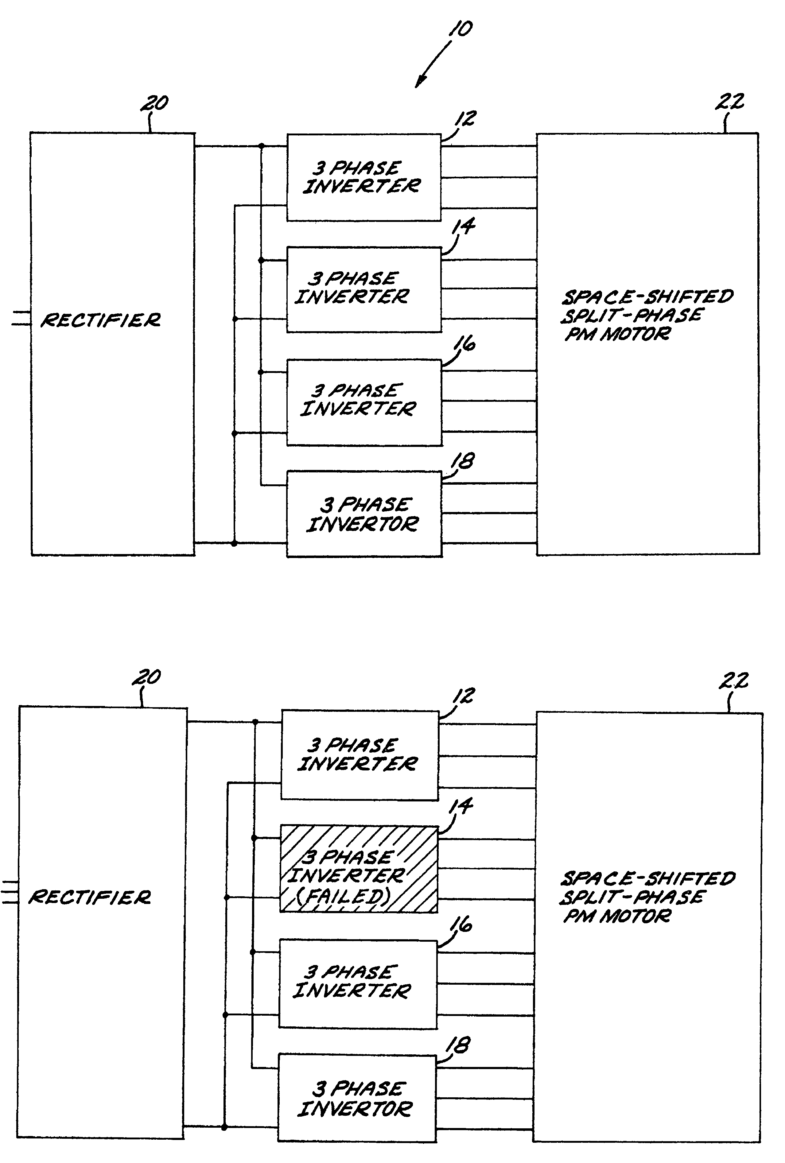
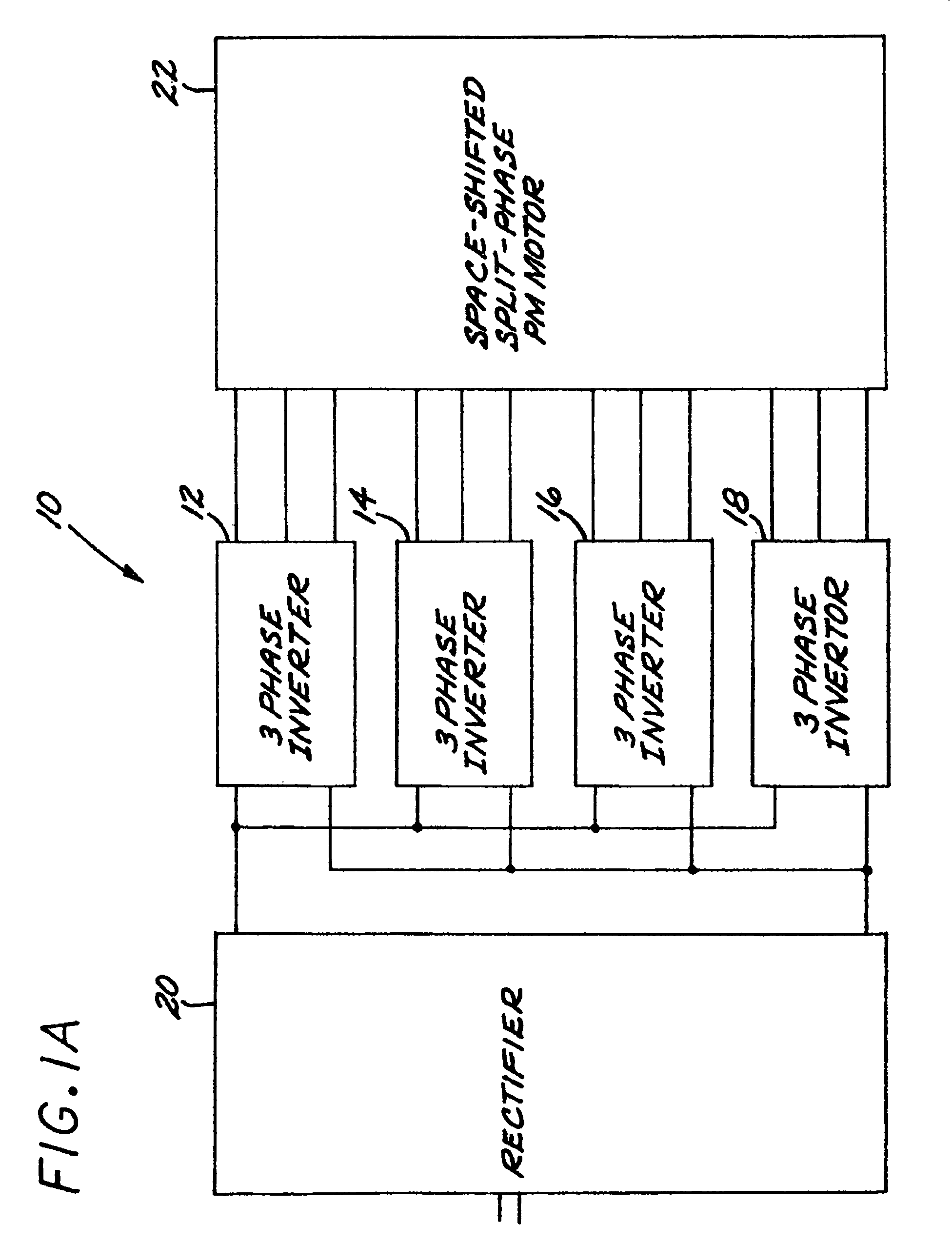
[0026]Referring now to FIG. 1A, a space-shifted, split-phase stator motor drive system 10 is illustrated and wherein the dc / ac inverter disclosed in co-pending application Ser. No. 11 / 751,450, now U.S. Pat. No. 7,710,081 issued on May 4, 2010, filed May 21, 2007 and assigned to the assignee of the present invention, is replaced with N number of three phase inverter modules 12, 14 . . . 18 (in this example, N equals 4). The output of rectifier 20 is coupled to the inputs of the inverter modules as shown. The output of the inverter modules are coupled to space-shifted split phase motor 22.

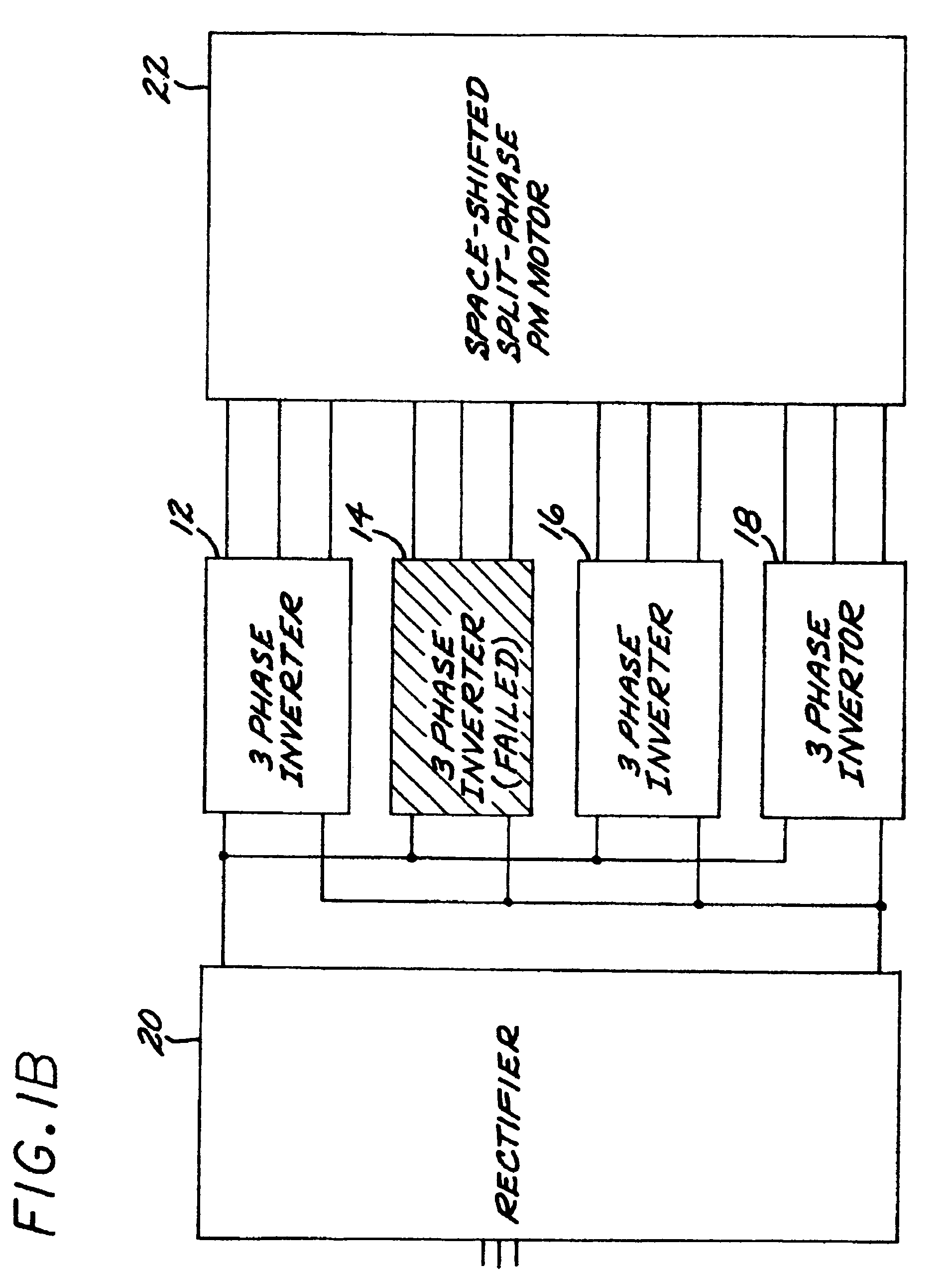
[0027]FIG. 1B is similar to FIG. 1A and illustrates the situation wherein 3 phase inverter 14 fails; in this case, the system is designed to increase the power output from operating inverter modules 12, 16 and 18 by 1 / (N−1).

[0028]FIG. 1C is similar to FIG. 1B with the addition of a spare inverter module 24. The active inverter modules 12, 14, 16 and 18 are connected to a switch matrix for connecting ...


PUM


Abstract

Circuit configurations for controlling an AC motor drive system wherein the control systems include redundancy features to compensate for possible failed system components.

Description

BACKGROUND OF THE INVENTION[0001]1. Field of the Invention[0002]The present invention provides a system for controlling an electric machine and providing redundancy for system components.[0003]2. Description of the Prior Art[0004]In a conventional power system, high speed motors are directly coupled to high speed machinery and controlled by a high frequency output, pulse width modulation based, AC drives. However, the size, weight, efficiency, operating costs and system availability of the drive systems make the high speed motors not widely utilized.SUMMARY OF THE INVENTION[0005]The present invention provides a system for controlling a space-shifted, split-phase stator AC motor drive system. The following topologies have been developed to implement the above control system:[0006]1. An AC motor drive system wherein a dc / ac inverter is divided into N number of inverter modules; a control strategy that allows a single inverter to go off-line and the power output on the each remaining m...

Claims


Application Information

Patent Timeline
Patent Type & Authority Patents(United States)
IPC IPC(8): G05B5/00
CPCH02M7/493H02P27/06H02M2001/0012H02M1/0012H02M1/0043
Inventor PAN, ZHIGUOSABAN, DANIEL M.AHMAD, RAED
Owner FMC TECH INC
Why Eureka
Try Eureka