Turbine engine blade, in particular for a one-piece bladed disk

a turbine engine and blade technology, applied in the direction of liquid fuel engines, vessel construction, marine propulsion, etc., can solve the problems of reducing the aerodynamic performance of the blade and the difficulty of controlling the aerodynamic flow behavior, and achieve good control of the secondary flow

Active Publication Date: 2014-11-20
SN DETUDE & DE CONSTR DE MOTEURS DAVIATION S N E C M A
View PDF0 Cites 37 Cited by
  • Summary
  • Abstract
  • Description
  • Claims
  • Application Information

AI Technical Summary

Benefits of technology

[0004]It is therefore desirable to be able to have a blisk blade with an airfoil profile that makes it possible to achieve good control over the secondary flows and to take account of the blade being located in a “plunging” passage.
[0006]Such an airfoil profile makes it possible in particular to obtain a fluid flow distribution that favors the zone of the airfoil close to the root compared with the mid-height zone. Furthermore, the flow rate is sucked against the top portion of the flow passage. This results in optimizing the distribution of the fluid flow over the entire height of the flow passage, thereby improving the aerodynamic efficiency of the blade and contributing to controlling the secondary flows.
[0010]Furthermore, the dihedral angle of the leading edge of the airfoil is advantageously negative between the root and the first radial height of the airfoil, and positive between a third radial height of the airfoil situated in the range 40% to 60% of the total radial height of the airfoil and the tip. The presence of such a dihedral angle serves to provide incidence protection to the low portion of the airfoil (the leading edge is said to be “closed”), which is associated with a zone of static stress that is acceptable.
[0011]The third radial height of the airfoil is advantageously situated at 50% of the total radial height of the airfoil. Thus, the forces imparted by the blading to the fluid (and vice versa) are oriented optimally for guaranteeing static stress in the airfoil that is acceptable and a distribution of aerodynamic efficiency that is uniform.

Problems solved by technology

These secondary flows contribute to reducing the aerodynamic performance of the blade.
The aerodynamic flow behavior is also made difficult to control by the presence of a flow passage of the “plunging” type, i.e. a passage that is sloping towards the axis of rotation of the turbojet.

Method used


Image

  • Turbine engine blade, in particular for a one-piece bladed disk
  • Turbine engine blade, in particular for a one-piece bladed disk

Examples


Embodiment Construction

[0018]The invention applies to any turbine engine blade.

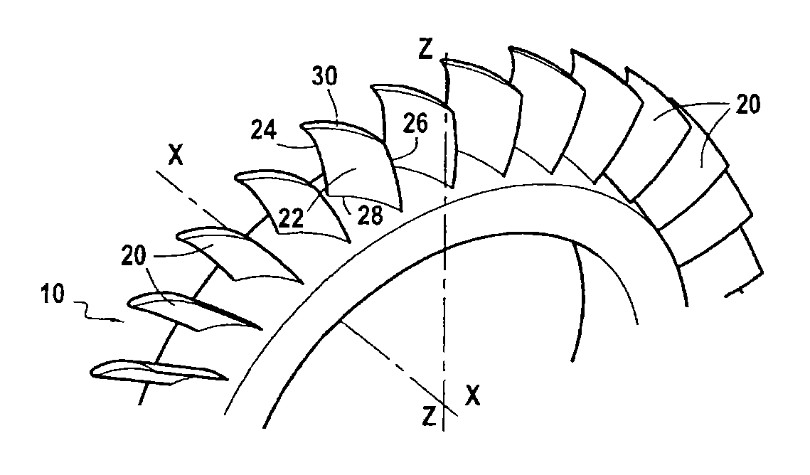
[0019]The invention relates more particularly but not exclusively to the blades of a one-piece bladed disk for a turbine engine, such as a disk 10 of the downstream stages of a high pressure compressor in a turbojet, like the disk shown in FIG. 1. The blades 20 of such a disk have an airfoil of small radial height, e.g. a height of the order of 25 millimeters (mm), and they are positioned in a “plunging” flow passage, i.e. a passage that slopes towards the axis of rotation of the turbojet.

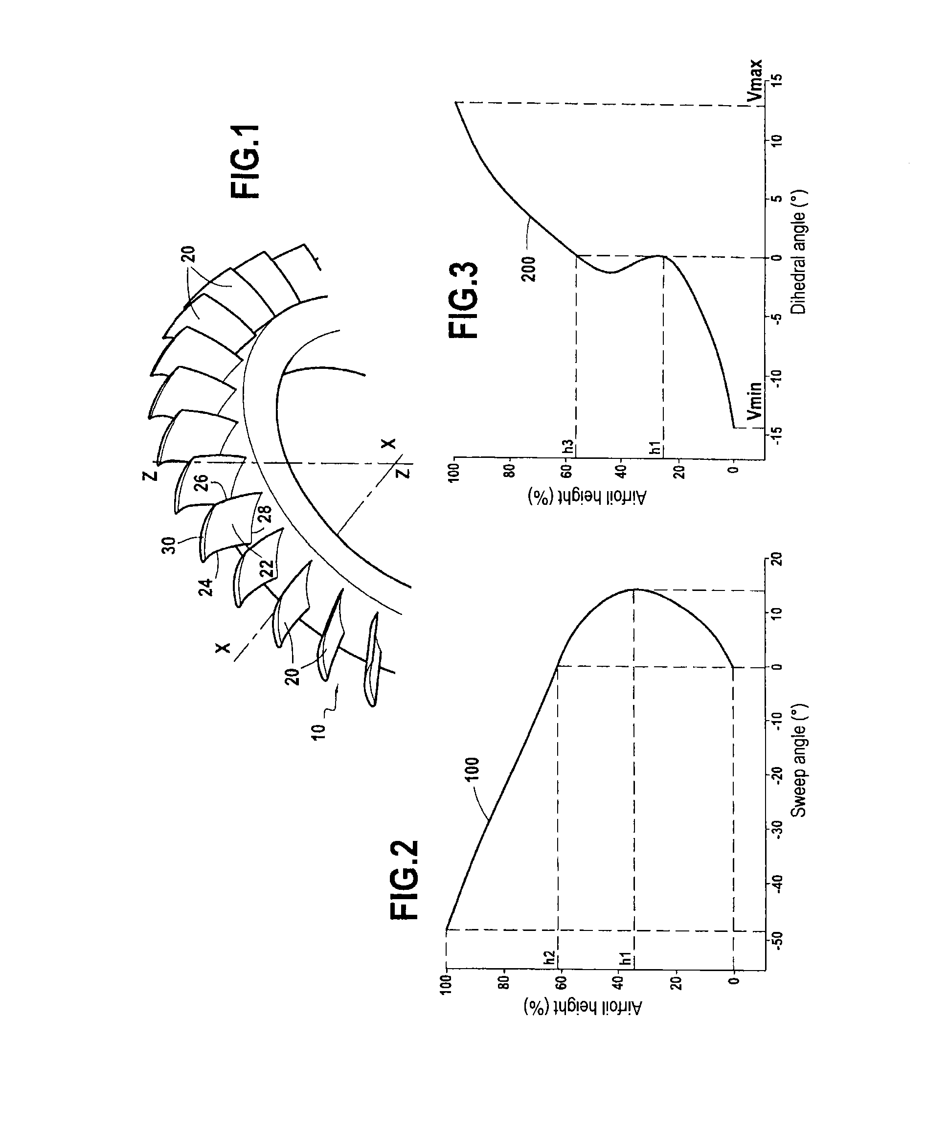
[0020]In known manner, each blade 20 comprises an airfoil 22 that extends axially (i.e. along the longitudinal axis X-X of the turbojet) between a leading edge 24 and a trailing edge 26, and that extends radially (i.e. along a radial axis Z-Z perpendicular to the longitudinal axis X-X) between a root 28 and a tip 30.

[0021]According to the invention, the leading edge 24 of the blade airfoil presents a sweep angle that is positive and that incre...


PUM


Abstract

A turbine engine blade comprising an airfoil extending axially between a leading edge and a trailing edge and extending radially between a root and a tip. The leading edge of the airfoil presents a sweep angle that is positive and that increases continuously from the root to a first radial height of the airfoil situated in the range 20% to 40% of the total radial height of the airfoil as measured from the root to the tip, and decreases continuously from this first radial height of the airfoil to the tip.

Description

BACKGROUND OF THE INVENTION[0001]The present invention relates to the general field of one-piece bladed disks for a turbine engine, and it relates more particularly to the profile of the blades included in such disks.[0002]A one-piece bladed disk of a turbine engine (also known as a “blisk”) designates a rotor in which the blades and the disk that carries them are machined directly in a single uniform block of metal so as to form one single piece. Such disks are generally used to form various compressor stages of the turbine engine, and in particular the high pressure compressor of an aviation turbojet of the two-spool bypass type.[0003]The design of blisk blades needs to satisfy requirements both in terms of aerodynamic performance and in terms of mechanical strength in a particular environment. When such blades present a radial airfoil height that is relatively small, high-amplitude aerodynamic phenomena known as secondary flows are generated. These secondary flows contribute to r...

Claims


Application Information

Patent Timeline
Patent Type & Authority Applications(United States)
IPC IPC(8): F01D5/14
CPCF01D5/141F05D2250/70F05D2240/242F01D5/34F04D29/324F05D2220/3216F05D2240/303F05D2250/71Y02T50/60
Inventor PERROT, VINCENT PAUL GABRIELCELLIER, DAMIENDUFRESNE, ALICIA LISE, JULIAPELLETRAU, PHILIPPE PIERRE MARCEL MARIERIOS, JEAN-FRANCOIS ANTOINE CHRISTIANVILLAINES, LAURENT CHRISTOPHE FRANCIS
Owner SN DETUDE & DE CONSTR DE MOTEURS DAVIATION S N E C M A
Why Eureka
Try Eureka