Flexible and Implantable Glucose Fuel Cell

a fuel cell, flexible technology, applied in cell components, sustainable manufacturing/processing, therapy, etc., can solve the problems of microbial fuel cells of the present generation that are not suitable for biological implanted applications, the least catalytic efficiency of the three design paradigms, and the limited life of the fuel cell, etc., to achieve the effect of improving the volumetric limit on oxidation or reduction current density, improving the volumetric power density, and being flexibl

Active Publication Date: 2014-11-20
MASSACHUSETTS INST OF TECH
View PDF3 Cites 15 Cited by
  • Summary
  • Abstract
  • Description
  • Claims
  • Application Information

AI Technical Summary

Benefits of technology

[0010]In this invention, a flexible and implantable glucose fuel cell is disclosed having improved volumetric power density by an order of magnitude over prior designs. During fabrication, the underlying substrate as well as at least one of the anode and cathode is produced in such a way that they have exceptional flexibility. This flexibility enables the construction of high-surface-area electrodes that fit within a small volume thus improving volumetric limits on oxidation or reduction current density at the electrode. Miniature prosthetic systems that function with needed steady-state power budgets can then be built to run on these fuel cells. Techniques that exploit resonant transformer action and efficient rectification may be used to efficiently convert even 20 mV energy-harvesting outputs to the 1-5 V levels needed for powering electronic chips.

Problems solved by technology

However, their lifetimes are often limited by the tendency of the enzymes to degrade and ultimately degenerate with time.
However, the prospect of implanting even non-pathogenic bacteria raises concerns of safety and biocompatibillty.
Thus, microbial fuel cells of the present generation are not yet suitable for biologically implanted applications.
As a result, solid-state catalysts represent the least catalytically efficient of the three design paradigms identified above.
However, these power levels are still relatively small.

Method used


Image

  • Flexible and Implantable Glucose Fuel Cell
  • Flexible and Implantable Glucose Fuel Cell
  • Flexible and Implantable Glucose Fuel Cell

Examples


Embodiment Construction

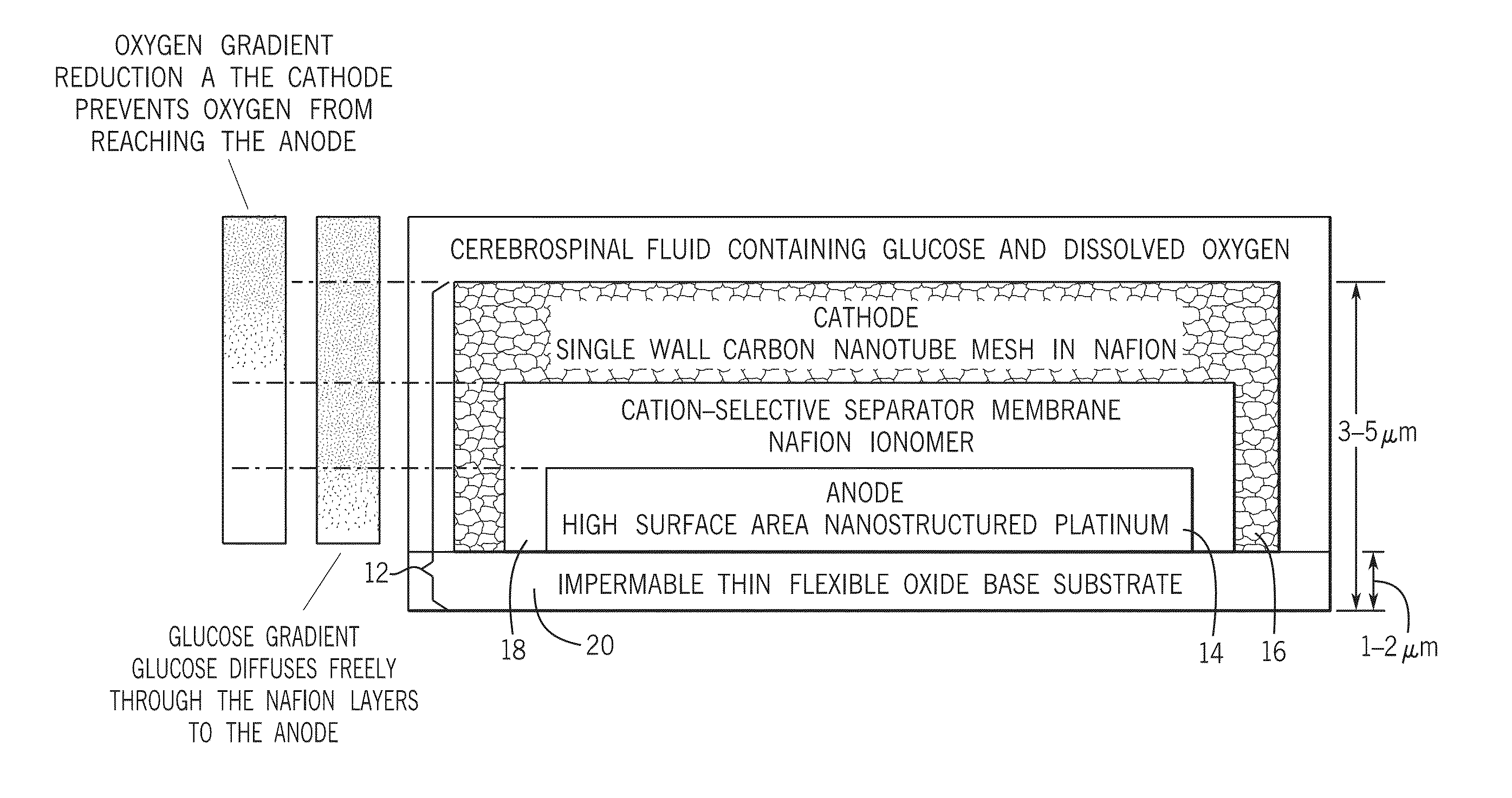
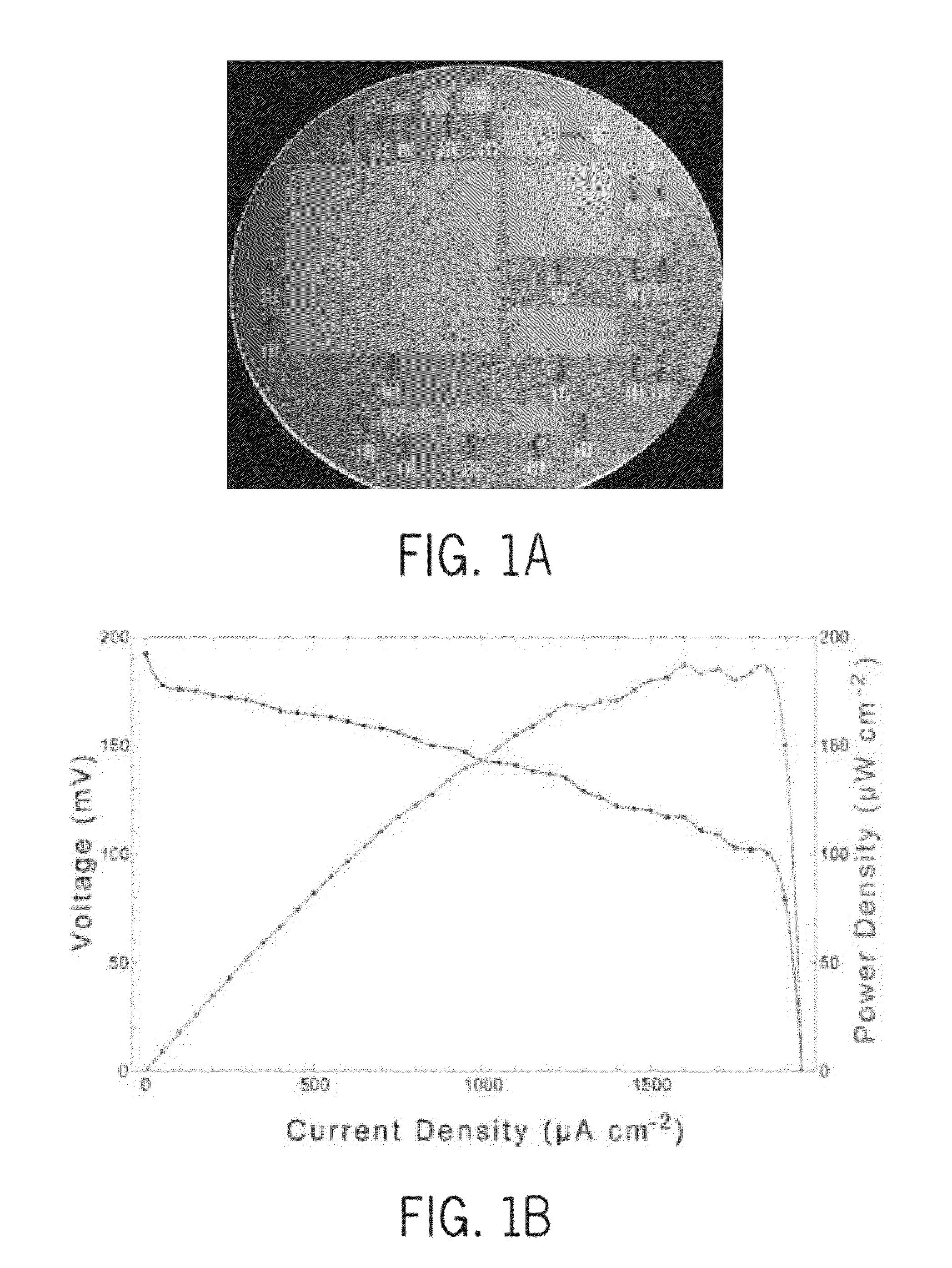
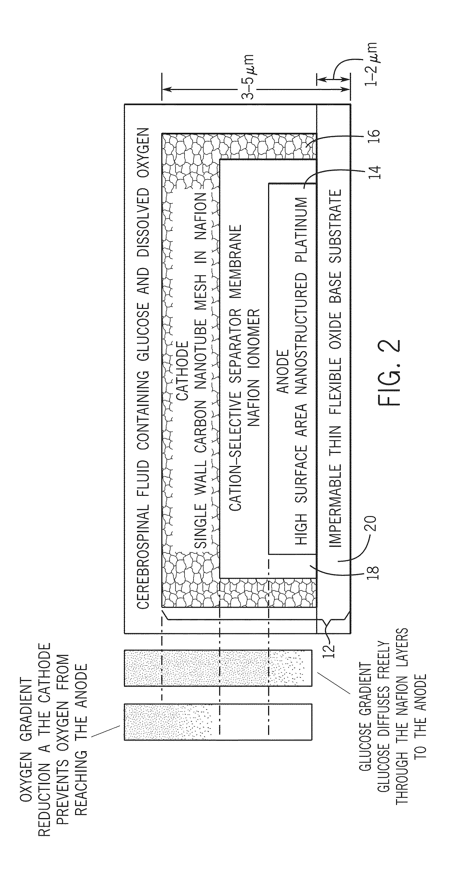
[0032]Referring first to FIGS. 2 and 3, a solid-state glucose fuel cell design according to one aspect of the invention is illustrated. The solid state glucose fuel cell 10 uses a half-open, two-chamber design that is sized and shaped to fit a particular anatomic compartment, and is constructed using semiconductor fabrication techniques as will be described in greater detail below. To provide context for the description that follows, it is contemplated that this glucose fuel cell 10 may be received into a given constrained volume of implantation in a vertebrate in which the glucose fuel cell has access to cerebrospinal fluid including glucose. Among other things, cerebrospinal fluid contains glucose, but is relatively free from other substances that may foul the reactive surfaces of the fuel cell 10 and negatively impact the efficiency of the fuel cell 10. In such application, the glucose fuel cell 10 is relatively small in size and form factor having a footprint that does not excee...


PUM

PropertyMeasurementUnit
thickaaaaaaaaaa
volumesaaaaaaaaaa
open circuit voltageaaaaaaaaaa

Abstract

A glucose fuel cell for reception into a given constrained volume of implantation in a vertebrate in which the glucose fuel cell has access to fluid containing glucose. The fuel cell includes an anode adapted to oxidize the glucose, a cathode adapted to reduce an oxidant, and a membrane disposed between the anode and the cathode and separating the anode from the cathode. At least one of the anode or cathode define a flexible sheet that is geometrically deformed to be receivable into the given constrained volume of implantation and increase volumetric power density. Related methods of making a glucose fuel cell of this type and implantable assemblies including the glucose fuel cell are also disclosed.

Description

CROSS-REFERENCE TO RELATED APPLICATIONS[0001]This application claims the benefit of U.S. provisional patent application Ser. No. 61 / 824,647 filed on May 17, 2013, the contents of which are incorporated by reference for all purposes as if set forth in their entirety herein.STATEMENT OF FEDERALLY SPONSORED RESEARCH OR DEVELOPMENT[0002]This invention was made with Government support under Grant No. R01 NS056140 awarded by the National Institutes of Health and by Grant No. 1332250 awarded by the National Science Foundation. The United States Government has certain rights in the invention.BACKGROUND[0003]This invention relates to glucose fuel cells for use in the body. In particular, this invention relates to improvements in the volumetric power densities of glucose fuel cells.[0004]In a glucose-based biofuel cell, glucose is oxidized at the anode, while oxygen is reduced to water at the cathode. The nature of the catalyst residing at the anode influences the extent of glucose oxidation ...

Claims


Application Information

Patent Timeline
Patent Type & Authority Applications(United States)
IPC IPC(8): H01M8/16
CPCH01M8/16A61B5/14532A61B5/686A61N1/3785H01M4/8626H01M4/8652H01M4/8663H01M4/8867H01M4/8882H01M4/90H01M4/921H01M4/98H01M8/004H01M8/0208H01M8/1009H01M8/1039H01M8/1076H01M8/1081H01M8/1097H01M2008/1095Y02E60/50Y02P70/50
Inventor SARPESHKAR, RAHULMULDAVIN, JEREMY BERTTHORSEN, TODD ADDISONKEDZIERSKI, JAKUBRAPOPORT, BENJAMIN ISAACFEE, MICHALE SEAN
Owner MASSACHUSETTS INST OF TECH
Why Eureka
Try Eureka