

Implant Tack and Methods of Use Thereof
a technology of implants and tacks, applied in the field of implants, can solve the problems of jaw bone deterioration, additional tooth problems, and facial profile collapse,
- Summary
- Abstract
- Description
- Claims
- Application Information
AI Technical Summary
Benefits of technology
Problems solved by technology
Method used
Image

Examples
Embodiment Construction
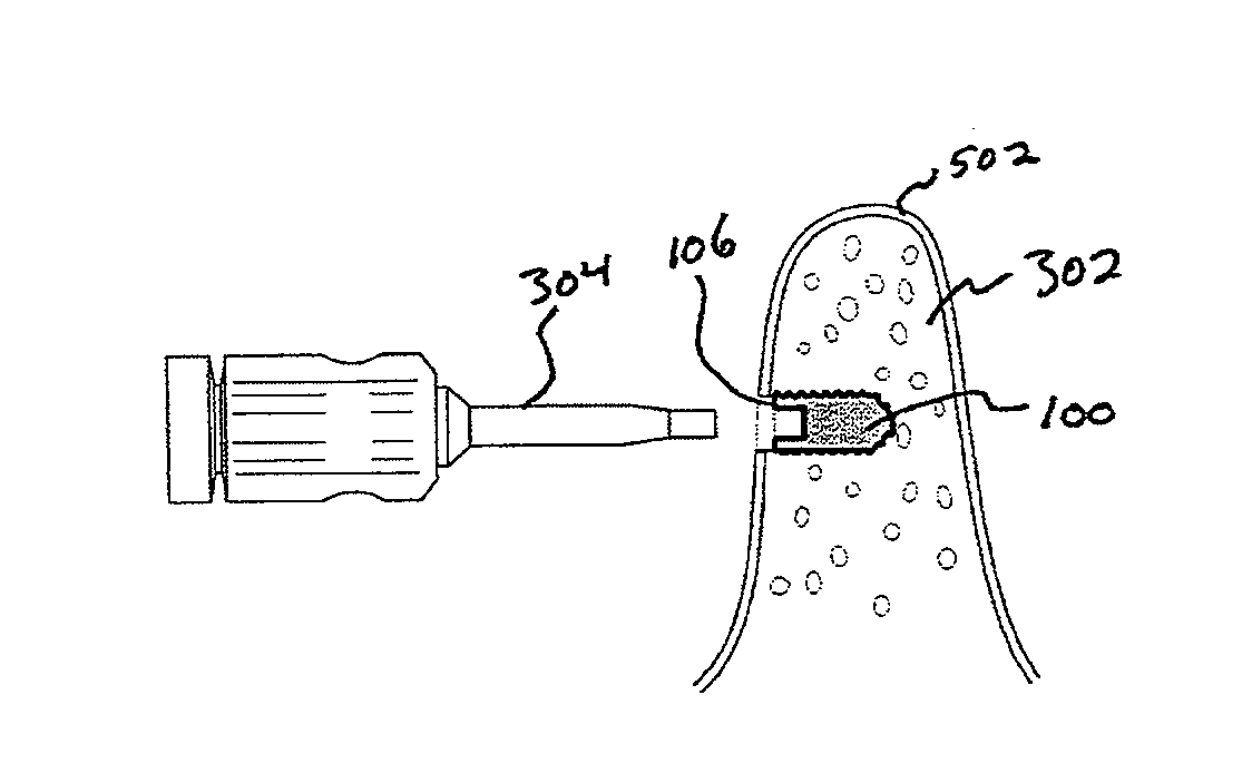
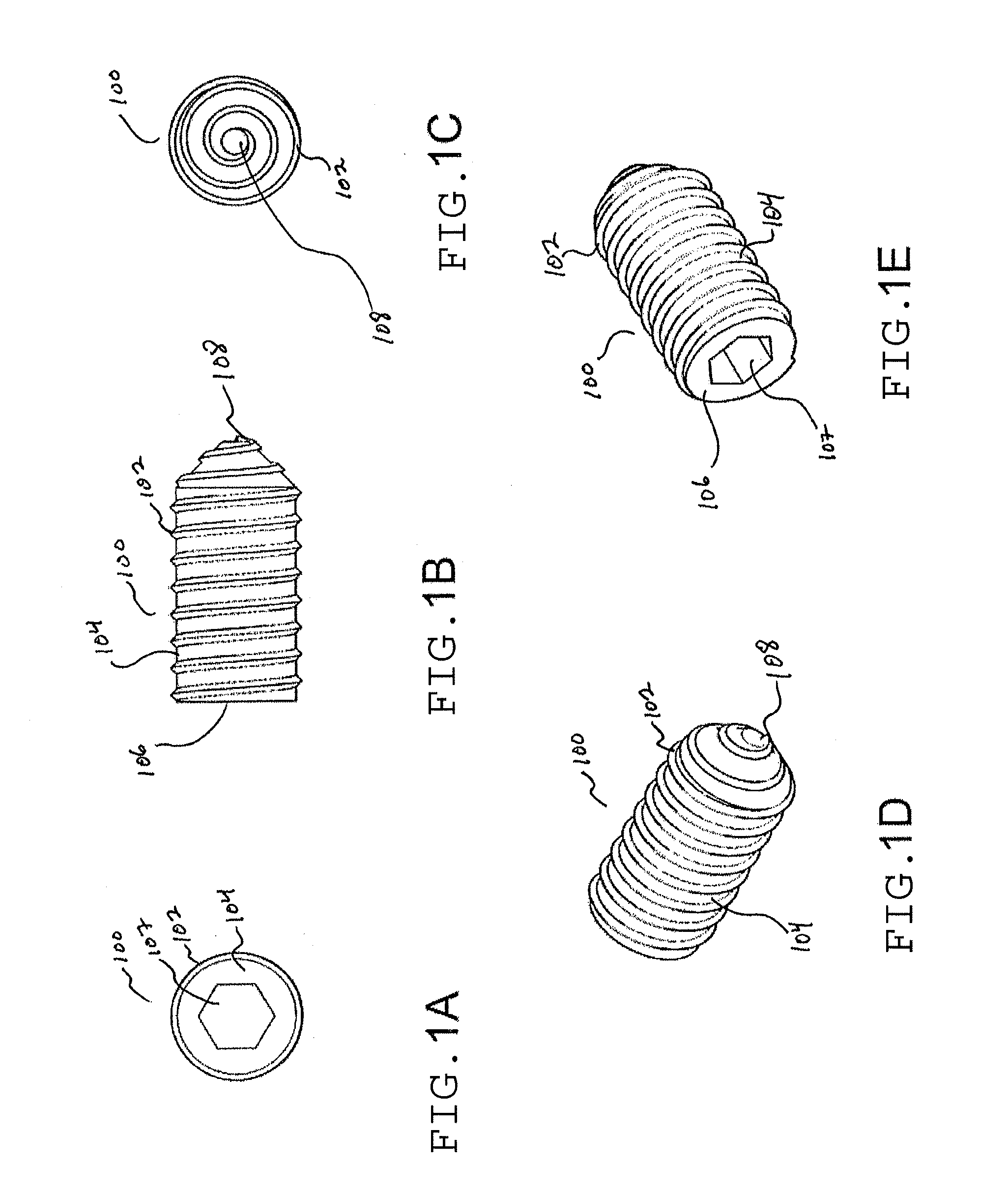
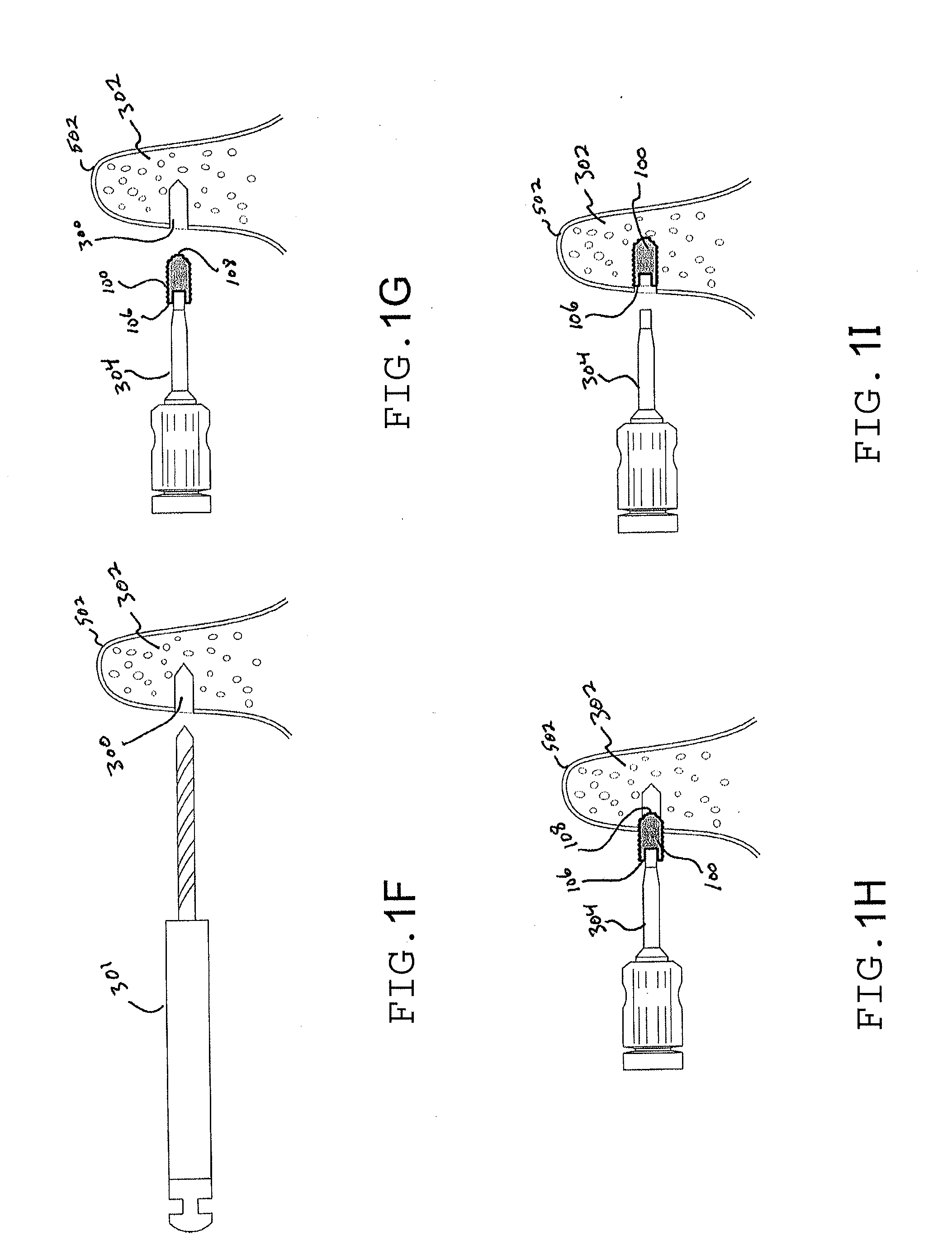
[0016]Illustrative and alternative embodiments of the implant tack and processes of use thereof are described in reference to the figures that accompany this application. While illustrative embodiments of the invention are shown in the figures of this application and are described generally as an implant tack, alternative embodiments of the invention as well as its features, components, and functionality are also described in this application. The implant tack is non-load bearing, i.e., it does not support an abutment for a crown or denture attachment. Its purpose is to osseointegrate with bone tissue surrounding the implant location in order to help preserve current bone levels. The implant tack is considered an endosteal implant because it will osseointegrate. There are other types of dental implants, e.g., blade implants, subperiosteal implants, etc., which do not osseointegrate. The implant tacks of the present invention must be capable of osseointegration. Any reference to “imp...
PUM
 Abstract
Description
Claims
Application Information