Adjustable Implant and Insertion Tool

a technology of adjustable implants and insertion tools, which is applied in the field of adjustable implants and adjustable implant insertion tools, can solve the problems of disc space collapse, disc herniation or protrusion, and various problems or disease states

Active Publication Date: 2014-11-20
K2M
View PDF24 Cites 160 Cited by
  • Summary
  • Abstract
  • Description
  • Claims
  • Application Information

AI Technical Summary

Benefits of technology

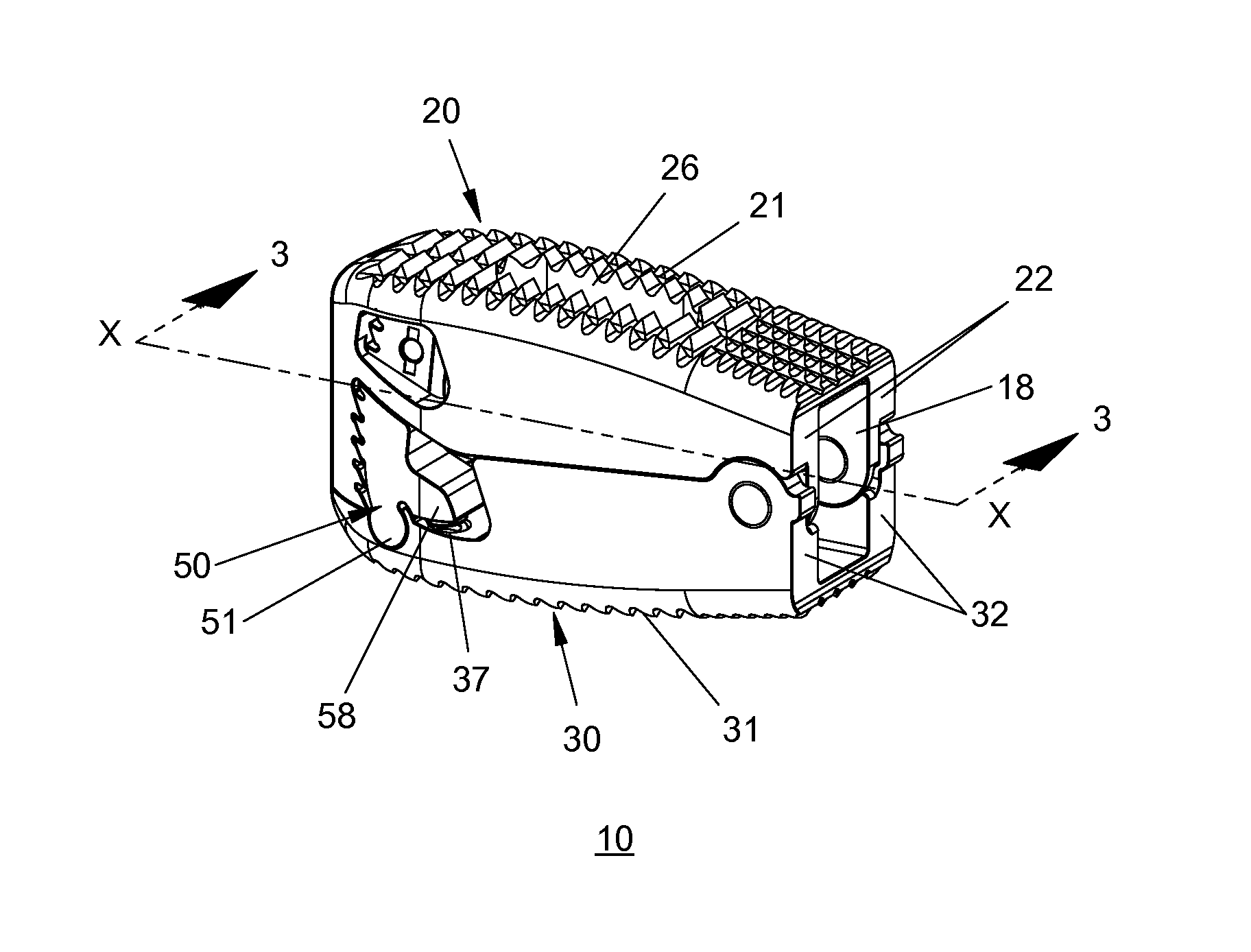
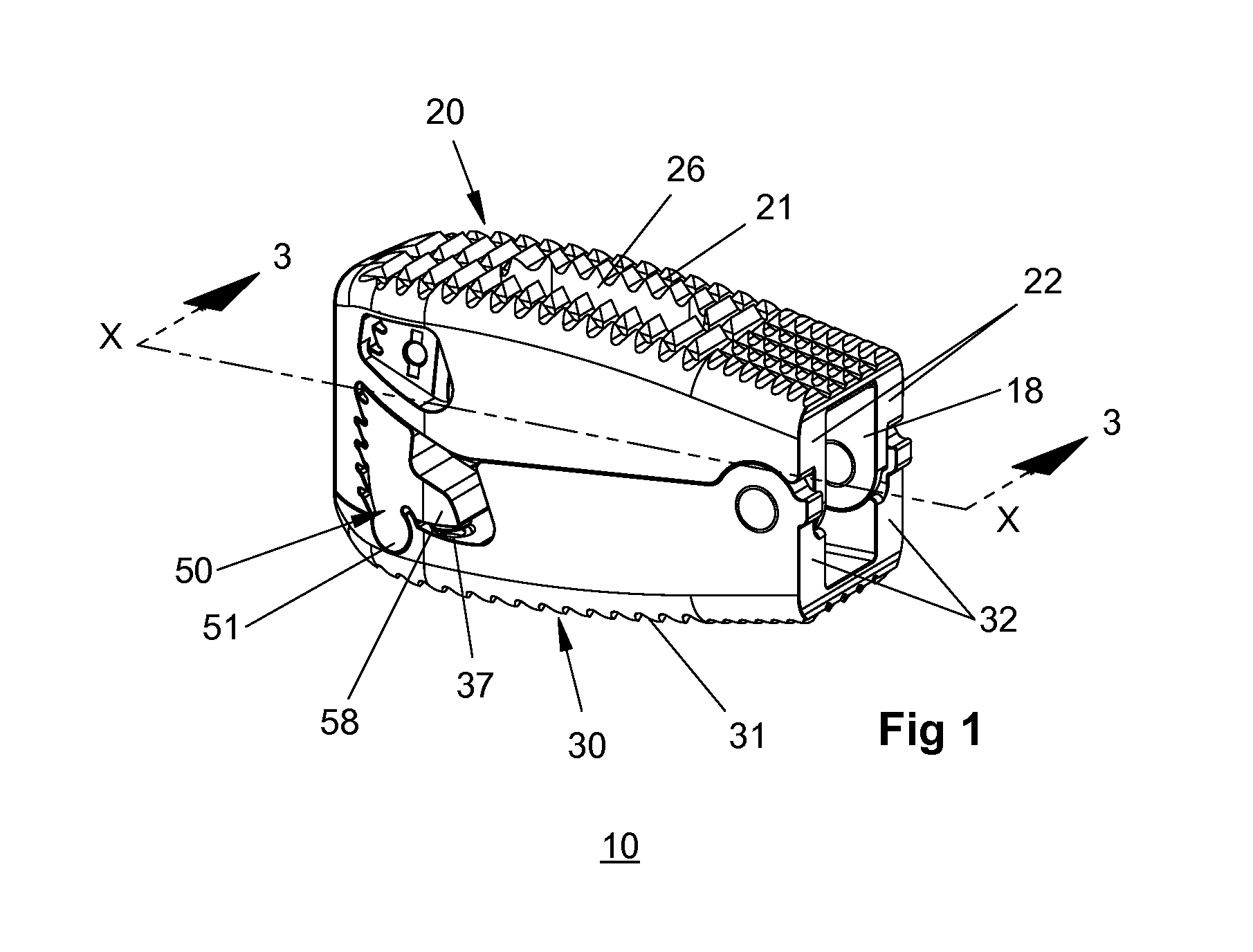
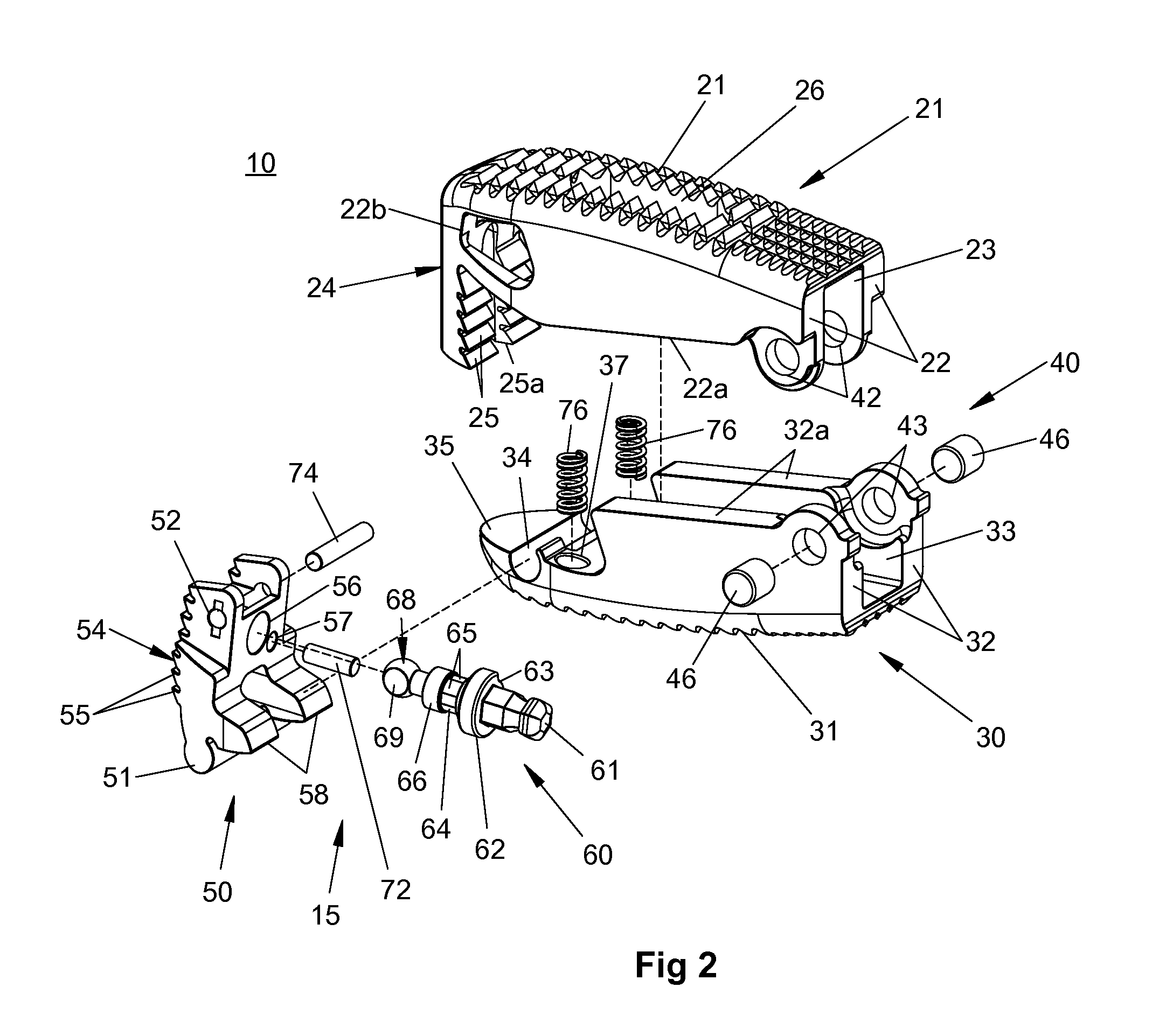
[0017]In some aspects, a proximal face of the locking flange includes teeth and a distal face of the locking pawl includes teeth opposing the teeth of the locking flange. In the locked state of the locking key the teeth of the locking flange and the teeth of the locking pawl are engaged with each other to prevent the upper and lower bodies from moving relative to one another and in the unlocked state of the locking key the teeth of the locking flange may be slidable over the teeth of the locking pawl to permit the upper and lower bodies to move relative to one another. In the unlocked state of the locking key, the upper and lower bodies may be moveable away from one another. In the unlocked state of the locking key, the upper and lower bodies may be prevented from moving towards one another.

Problems solved by technology

Stresses acting upon the human backbone (or “vertebral column”) may result in a variety of problems or disease states.
Disruption of a disc's internal architecture leads to bulging, herniation, or protrusion of pieces of the disc and eventual disc space collapse.
Any resulting irritation (e.g., mechanical or chemical) of surrounding neural elements (e.g., spinal cord and nerves) may cause pain that is attended by varying degrees of disability.
In addition, loss of disc space height relaxes tension on the longitudinal spinal ligaments, thereby contributing to varying degrees of spinal instability such as spinal curvature.
While cancellous bone appears ideal to provide the biologic components necessary for osseous union to occur, it does not initially have the strength to resist the tremendous forces that may occur in the intervertebral disc space, nor does it have the capacity to adequately stabilize the spine until long term boney union occurs.
For these reasons, interbody fusion using bone alone may have an unacceptable rate of bone graft migration, expulsion, or nonunion due to structural failures of the bone or residual degrees of motion that retard or prohibit boney union.
During implantation from an anterior approach (i.e., from the front of the body), excessive retraction (i.e., pulling) is often required on the great blood vessels which may damage the great blood vessels resulting in vascular tears or thrombosis.
On the other hand, during a posterior approach, large implant diameters may require excessive traction on neural elements for adequate placement, even if all posterior boney elements are removed.
In some instances, an adequate implant size cannot be inserted posteriorly, particularly if there is a significant degree of ligamentous laxity requiring higher degrees of distraction to obtain stability by tightening the annular ligamentous tension band.
Compromising on implant size risks sub-optimal stability or a loose implant, which has a greater chance for migration within or expulsion from the disc space.
The alternative of excessively retracting neural elements to facilitate a posterior implant application may result damage to the neural elements.

Method used


Image

  • Adjustable Implant and Insertion Tool
  • Adjustable Implant and Insertion Tool
  • Adjustable Implant and Insertion Tool

Examples


Embodiment Construction

[0045]Embodiments of the present disclosure are now described in detail with reference to the drawings in which like reference numerals designate identical or corresponding elements in each of the several views. As used herein, the term “clinician” refers to a doctor, a nurse, or any other care provider and may include support personnel. Throughout this description, the term “proximal” will refer to the portion of the device or component thereof that is closer to the clinician and the term “distal” will refer to the portion of the device or component thereof that is farther from the clinician. In addition, the term “cephalad” is used in this application to indicate a direction toward a patient's head, whereas the term “caudad” indicates a direction toward the patient's feet. Further still, for the purposes of this application, the term “lateral” indicates a direction toward a side of the body of the patient, i.e., away from the middle of the body of the patient. The term “posterior”...


PUM


Abstract

An adjustable spinal implant includes a lower body, an upper body, a locking pawl, and a locking key. The upper body and the lower body are pivotable relative to one another between a collapsed position and an expanded position. The upper body includes a locking flange that extends towards the lower body. The locking pawl is coupled to the lower body and is moveable between a locked position such that the upper and lower bodies are fixed relative to the one another and an unlocked position such that the upper and lower bodies are moveable relative to one another. The locking key is moveable between a locked state such that the locking pawl is fixed in the locked position and an unlocked state wherein the locking pawl is moveable between the locked position and the unlocked position.

Description

CROSS-REFERENCE TO RELATED APPLICATIONS[0001]The present application claims the benefit of and priority to U.S. Provisional Patent Application Ser. No. 61 / 825,117 filed on May 20, 2013, the entire contents of which are incorporated herein by reference.BACKGROUND[0002]1. Technical Field[0003]The present disclosure relates to a device for use in orthopedic surgeries and, more specifically, to an adjustable implant, an insertion tool for an adjustable implant, and a method for inserting an adjustable implant into an intervertebral space.[0004]2. Discussion of Related Art[0005]Adjustable implants may serve to stabilize adjacent vertebral elements, thereby facilitating the development of a boney union between them and thus long term spinal stability. Stresses acting upon the human backbone (or “vertebral column”) may result in a variety of problems or disease states.[0006]For example, intervertebral discs have a high propensity to degenerate. Overt or covert trauma occurring in the cours...

Claims


Application Information

Patent Timeline
Patent Type & Authority Applications(United States)
IPC IPC(8): A61F2/44A61F2/46
CPCA61F2/46A61F2/442A61F2/4611A61F2002/2817A61F2002/2835A61F2002/30266A61F2002/30281A61F2002/30484A61F2002/30522A61F2002/30538A61F2002/3054A61F2002/30556A61F2002/30568A61F2002/30594A61F2002/30828A61F2002/30831A61F2002/448A61F2/4425A61F2/447A61F2002/30624A61F2002/30593
Inventor SUDDABY, LOUBERTMCCLINTOCK, LARRY
Owner K2M
Why Eureka
Try Eureka