Gas insulated switchgear and manufacturing method of the same
a technology of switchgear and gas insulation, which is applied in the direction of plastic/resin/waxes insulators, organic gas insulators, coatings, etc., can solve the problems of deterioration, significant deterioration, and inferior gas performance of sf/sub>6/sub>gas in insulation performance, so as to suppress the development of discharge and enhance the reliability of gas insulated switchgear. , the effect of improving the degree of deterioration
- Summary
- Abstract
- Description
- Claims
- Application Information
AI Technical Summary
Benefits of technology
Problems solved by technology
Method used
Image

Examples
first embodiment
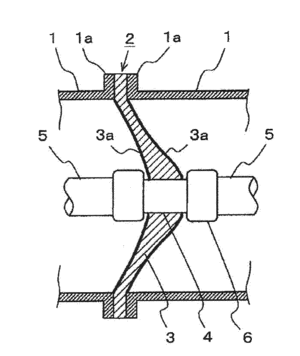
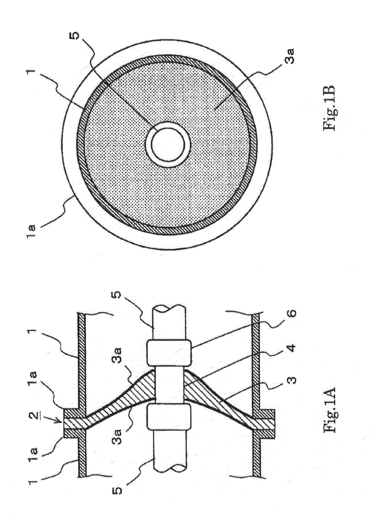
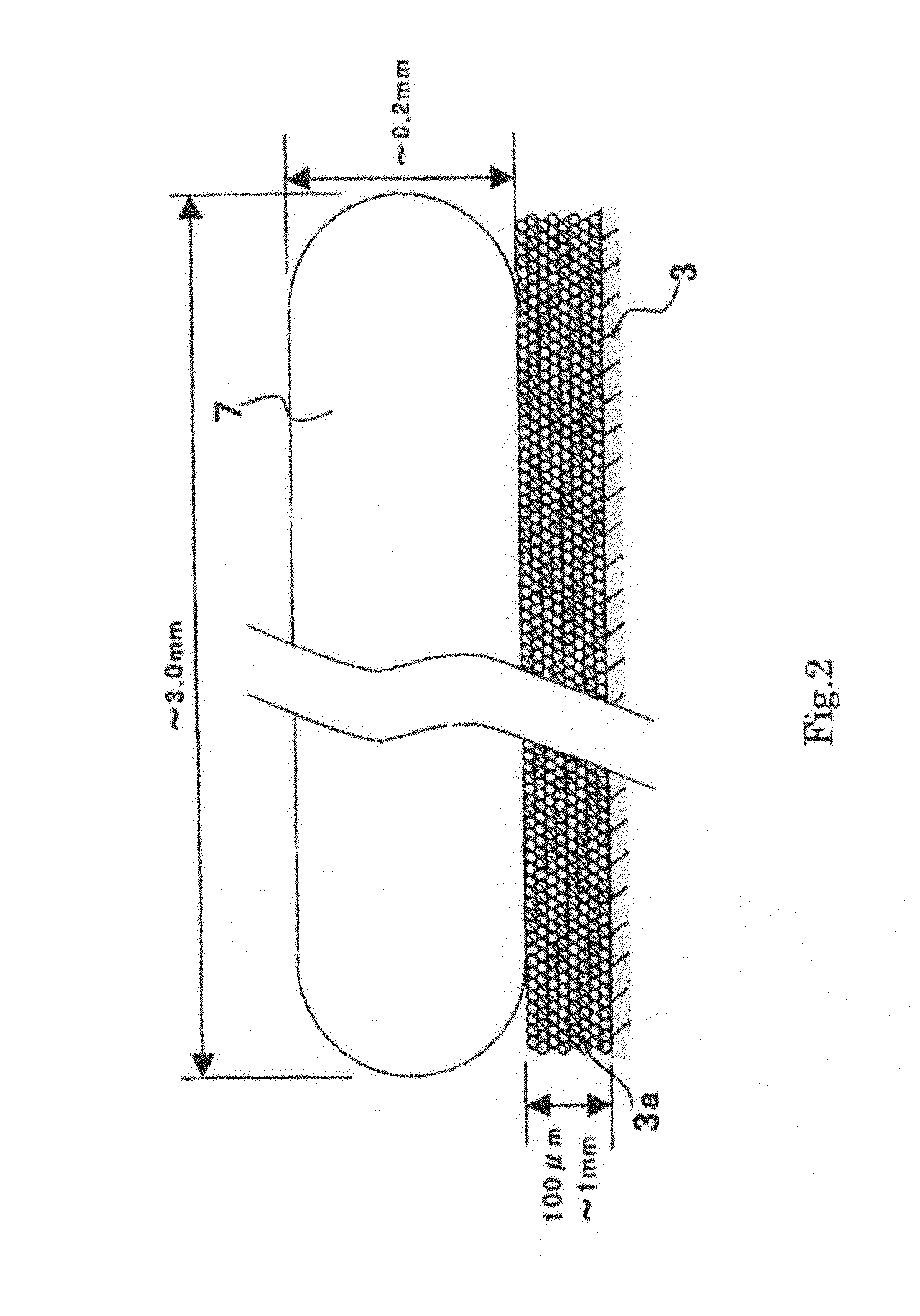
[0025]FIG. 1 is a view showing a portion of an insulation spacer in a gas insulated switchgear according to a first embodiment of the invention. FIG. 1A is a sectional side view and FIG. 1B is a front view of the portion of the insulation spacer when viewed from an axial direction of a tank. Also, FIG. 2 is an enlarged cross section of a surface of the insulation spacer of FIG. 1 to show a state in which metal foreign matter adheres to the surface.
[0026]Firstly, the gas insulated switchgear will be described schematically with reference to FIG. 1.
[0027]Ground tanks 1 of a predetermined length each formed of a cylindrical metal container are connected in portions of flanges 1a at respective ends with unillustrated bolts or the like. An insulation spacer 2 shaped like a conical surface (side surface portion of a cone), which is an insulation structural member, is sandwiched between connection surfaces of the flanges 1a and fixed by being bolted together with the flanges 1a. The insula...
second embodiment
[0071]A gas insulated switchgear according to a second embodiment of the invention will now be described. Because a fundamental shape of the insulation spacer supporting the high-voltage conductor in the gas insulated switchgear is the same as those in FIG. 1, FIG. 6 and FIG. 7 of the first embodiment above, illustrations and a description of the configuration are omitted and a difference will be chiefly described herein. The difference is a range across which the cover film having ablation performance covers the surface of the insulation portion 3 of the insulation spacer 2.
[0072]FIG. 8 is a front view of a portion of an insulation spacer in the gas insulated switchgear of the second embodiment and this drawing corresponds to FIG. 1B of the first embodiment above.
[0073]In the first embodiment above, as is shown in FIG. 1, the cover film 3a (10a and 14a) is formed as a mixed layer obtained by mixing the powder 31 of any of thermoplastic resin, glass, cellulose, and polymer resin mad...
third embodiment
[0081]A third embodiment relates to a forming method of the cover film 3a (10a and 14a) formed on the insulation portion surface of the insulation spacer in a gas insulated switchgear equivalent to the counterpart described in the first or second embodiment. Because the configuration of the gas insulated switchgear is the same as those shown in FIG. 1, FIG. 6, and FIG. 7, illustrations and a description are omitted herein.
[0082]As has been described, the cover film 3a (10a and 14a) is formed by a step of obtaining a mixed coating material by mixing the powder 31 made of an ablation material with the epoxy resin 32, and a step of obtaining the cover film 3a made of the powder 31 mixed in the epoxy resin 32 by applying the mixed coating material on the surface of the insulation spacer 2 followed by allowing the epoxy resin 32 to cure, and the powder 31 remains in the form of particles after the cover film 3a is formed.
[0083]A first forming method of the cover film 3a will now be descr...
PUM
| Property | Measurement | Unit |
|---|---|---|
| Temperature | aaaaa | aaaaa |
| Particle size | aaaaa | aaaaa |
| Weight | aaaaa | aaaaa |
Abstract
Description
Claims
Application Information
 - R&D
- Intellectual Property
- Life Sciences
- Materials
- Tech Scout
- Unparalleled Data Quality
- Higher Quality Content
- 60% Fewer Hallucinations
Browse by: Latest US Patents, China's latest patents, Technical Efficacy Thesaurus, Application Domain, Technology Topic, Popular Technical Reports.
© 2025 PatSnap. All rights reserved.Legal|Privacy policy|Modern Slavery Act Transparency Statement|Sitemap|About US| Contact US: help@patsnap.com