
Electric Machine

a technology of electric machines and stators, applied in the direction of dynamo-electric machines, electrical apparatus, magnetic circuits, etc., can solve the problems of reducing the output of electric machines, unable to design compactly, and unable to meet the needs of electric machines, so as to improve the mechanical stability of the stator segment, improve the regulation characteristics, and high torque

Active Publication Date: 2014-11-27
SEW-EURODRIVE GMBH & CO KG
View PDF0 Cites 4 Cited by
  • Summary
  • Abstract
  • Description
  • Claims
  • Application Information

AI Technical Summary

Benefits of technology

The invention is about an electric machine, specifically a transversal flux machine, which has a stator composed of a stack of phase segments. Each segment has a stator bridge and pole shoes, and the pole shoes have a uniform shape. The stator segments are accommodated in a housing component, which is connected to the stator in a force-locking manner. The housing component is thermally shrink-fitted or bonded onto the stator. This allows for a simple and permanent connection. The electrical connections of the stator windings are easily routed outside of the machine. The invention also includes a method for detecting and adjusting the phase angle of the stator segments, which simplifies the production process.

Problems solved by technology

However, the bulbous shape is advantageously less bulbous than the second profile, because if the bulbous form of the second profile is exceeded, the winding space available for the stator winding becomes smaller and the output of the electric machine is reduced, which means that no compact design is possible.

Method used


Image

  • Electric Machine
  • Electric Machine
  • Electric Machine

Examples


Embodiment Construction

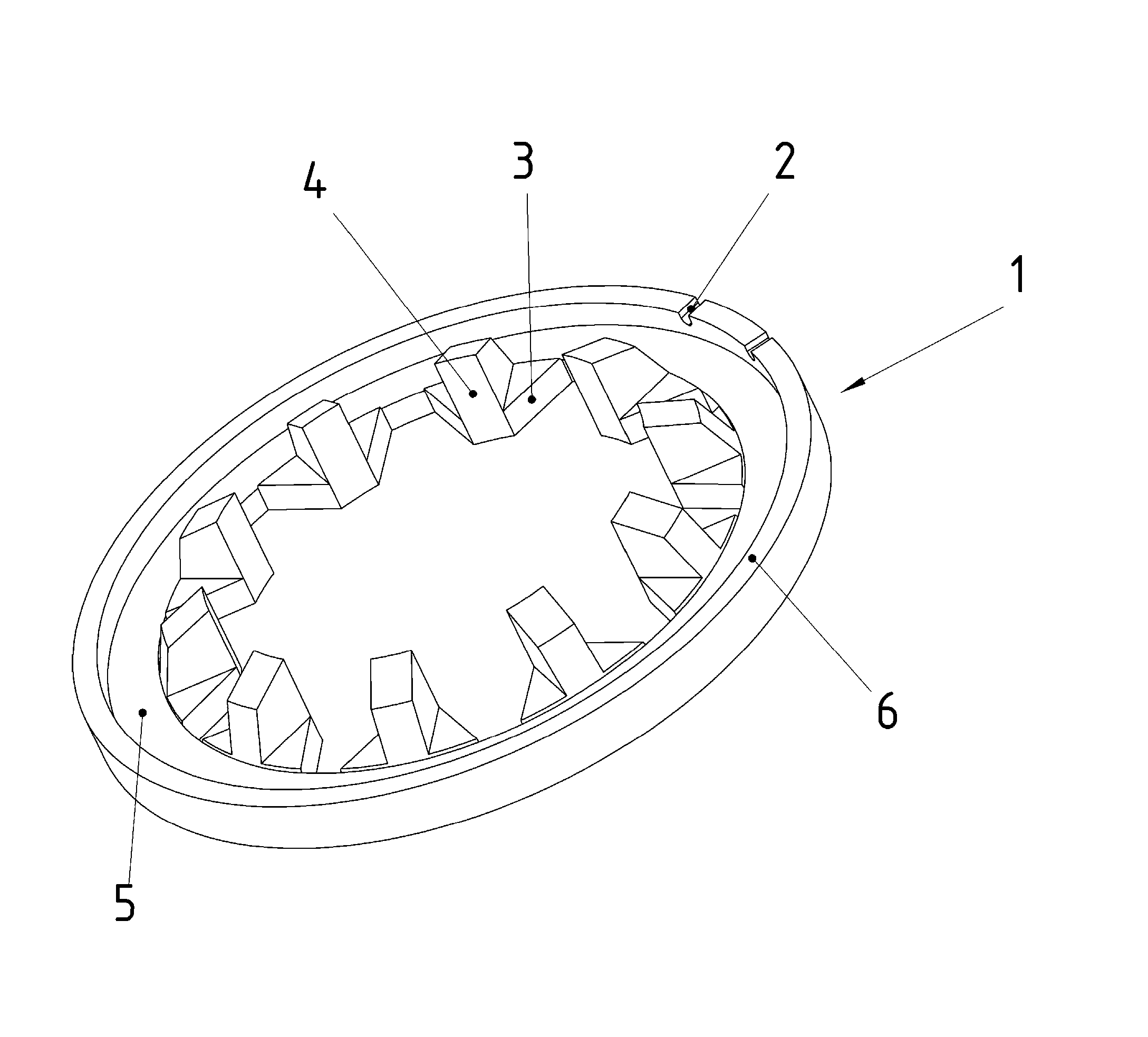
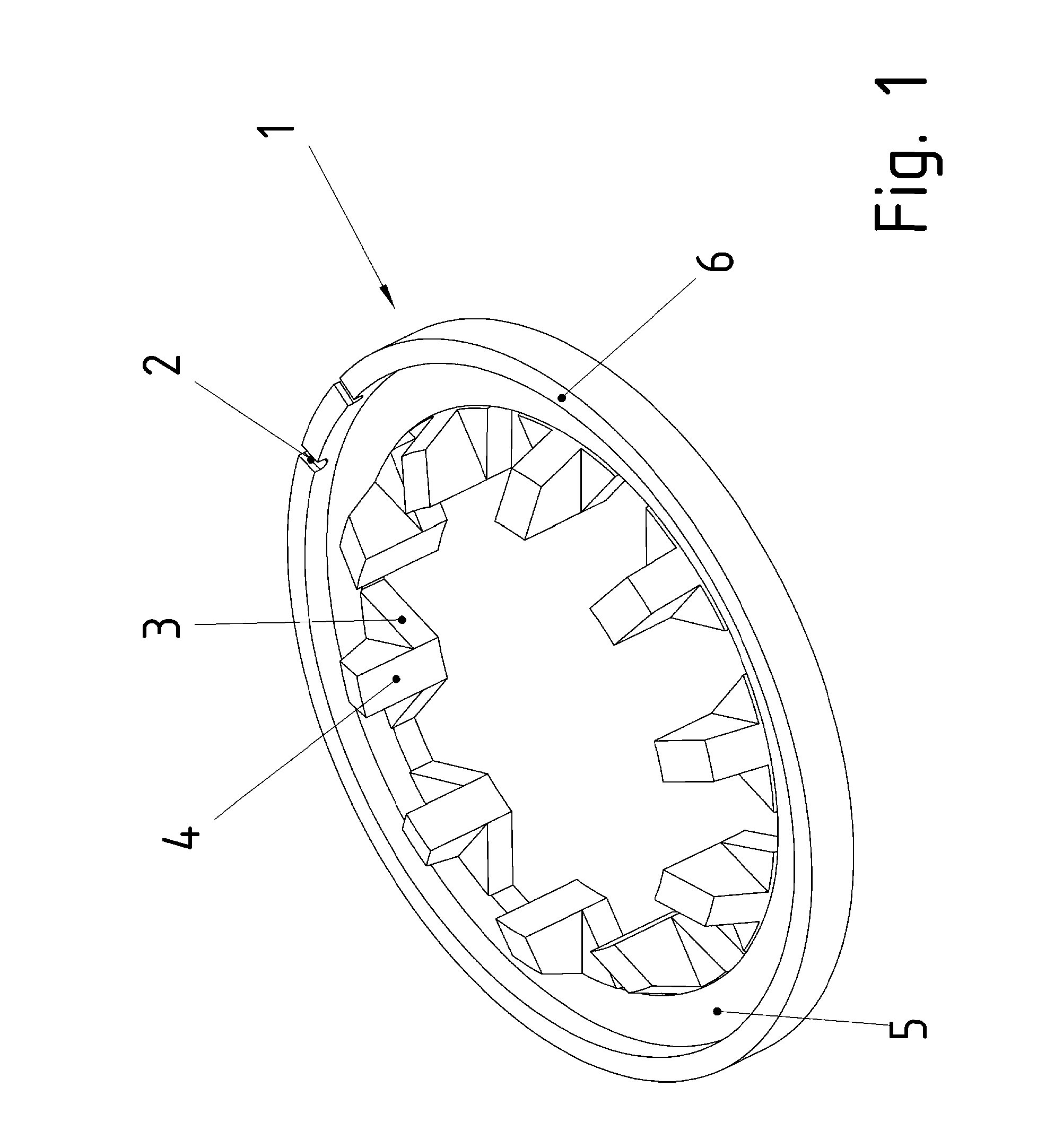
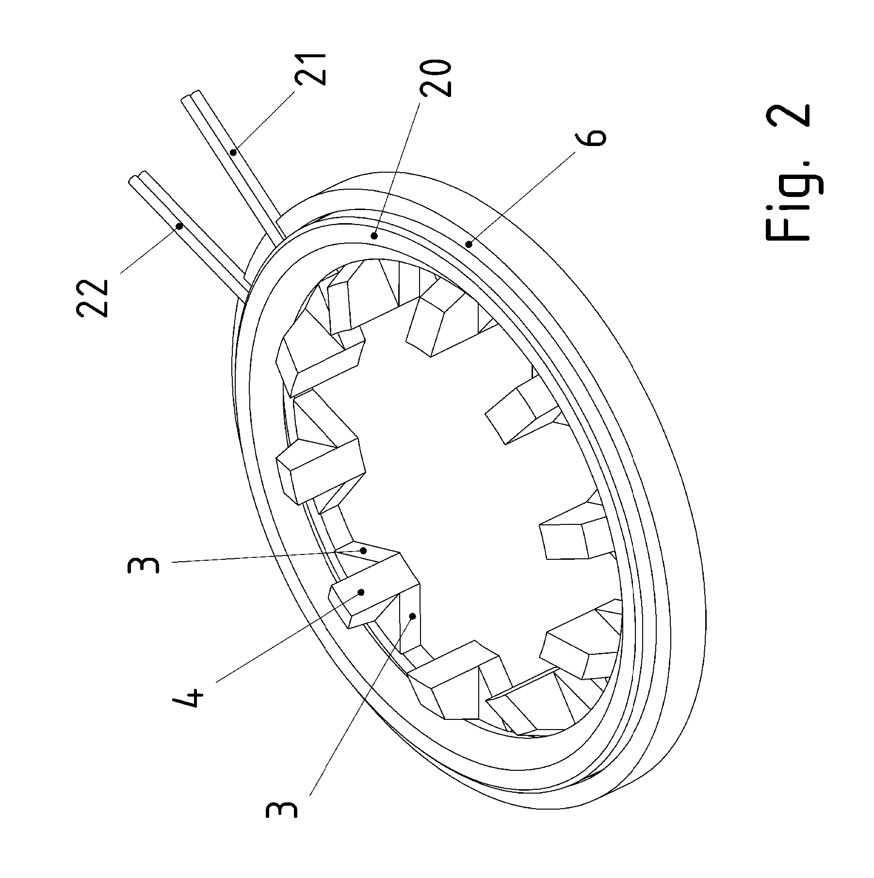
[0050]As illustrated in FIG. 1, stator segment 1 has pole shoes, which are pointing radially inward, i.e., toward the rotor (not shown), and which are evenly spaced apart in the circumferential direction.

[0051]The pole shoes are fixated by an annular stator bridge 5, which has a stator yoke 6 that axially projects at its radially outer end region, that is to say, in the direction of the rotor shaft axis.

[0052]The radially inwardly pointing area 4 of the pole shoe, i.e., the side of the pole shoe facing toward the air gap between stator and rotor, has a planar or curved design; in a curved design, a circular segment having the radius of the stator inner bore is used.

[0053]The active component of the rotor provided on the rotor and facing area 4, for example, may include permanent magnets, which are placed at regular intervals in the circumferential direction, the magnetization direction of permanent magnets situated next to each other in the circumferential direction being aligned in...


PUM

PropertyMeasurementUnit
temperatureaaaaaaaaaa
angleaaaaaaaaaa

Abstract

An electric machine, especially a transversal flux machine, the stator being composed of a stack of phase segments, each phase segment having at least one stator segment and one stator winding, especially a single winding, each stator segment having an annular stator bridge, on which pole shoes are premolded, which in particular extend in the radially inward direction, and / or which extend in the direction of the rotor and / or which are situated between the rotor and the annular stator bridge, the pole shoes having the same shape, in particular, the axial width of the pole shoe decreasing with increasing radial clearance, the associated profile being disposed between a first and a second profile, the first profile being a linear function of the radial clearance, the pole back associated with the first profile being a planar area, in particular, the second profile being a circular function, in particular a circular segment function, the pole back associated with the second profile being a cylindrical section area, in particular.

Description

FIELD OF THE INVENTION[0001]The present invention relates to an electric machine.BACKGROUND INFORMATION[0002]It is common knowledge that electric machines have a stator and a rotor, which is rotationally mounted in relation thereto and includes an active component. The stator produces one or more alternating field(s), which superpose to form a rotating field. A torque is produced in a reciprocal action with an excitation field of the rotor.SUMMARY[0003]Therefore, the present invention is based on the objective of further developing an electric machine in a compact manner, the production of which can be carried out in an uncomplicated manner.[0004]Important features of the invention in terms of the electric machine, especially a transversal flux machine, are that the stator is composed of a stack of phase segments,each phase segment has at least one stator segment and one stator winding, especially a single winding,each stator segment has an annular stator bridge, on which pole shoes...

Claims


Application Information

Patent Timeline
Patent Type & Authority Applications(United States)
IPC IPC(8): H02K1/14H02K3/32H02K15/02H02K5/04
CPCH02K1/14H02K15/022H02K3/32H02K5/04H02K1/145H02K3/525Y10T29/49009
Inventor DREHER, FLORIAN
Owner SEW-EURODRIVE GMBH & CO KG
Learn More