
DC-DC Converter With Circuit For Reproducing A Current Flowing Through A Storage Inductor

a technology of dc-dc converter and circuit, which is applied in the direction of dc-dc conversion, power conversion system, instruments, etc., can solve the problems of small limit frequency, expensive throttles and complex filter elements, and not generally the cas

Active Publication Date: 2014-11-27
HELLA KG HUECK & CO
View PDF2 Cites 12 Cited by
  • Summary
  • Abstract
  • Description
  • Claims
  • Application Information

AI Technical Summary

Benefits of technology

The patent describes a circuit that uses a current sensing resistor to detect the constant component of a current through a power inductor. This helps to avoid problems associated with sensing the alternating component of the current. However, the circuit may have its own oscillation tendency, but this can be stabilized by using a phase boosting element. The technical effect of the patent is to provide a more accurate and reliable current sensing mechanism for power conversion circuits.

Problems solved by technology

This results in small limit frequencies.
Otherwise, expensive throttles and complex filter elements are necessary in order to achieve the necessary protection from electromagnetic radiation (EMC).
However, this is not generally the case.
Therefore, it is generally not possible to make this compensation.
However, this results in high power dissipation.
The sampling of the signal by means of a sample and hold circuit is increasingly difficult at smaller resistance values, because the sampling takes a certain amount of time.
In this case as well, the sampled signal cannot be used.

Method used


Image

  • DC-DC Converter With Circuit For Reproducing A Current Flowing Through A Storage Inductor
  • DC-DC Converter With Circuit For Reproducing A Current Flowing Through A Storage Inductor

Examples


Embodiment Construction

[0042]In the following detailed description numerous specific details are set forth in order to provide a thorough understanding of the invention. However, it will be understood by those skilled in the art that the present invention may be practiced without these specific details. For example, the invention is not limited in scope to the particular type of industry application depicted in the figures. In other instances, well-known methods, procedures, and components have not been described in detail so as not to obscure the present invention.

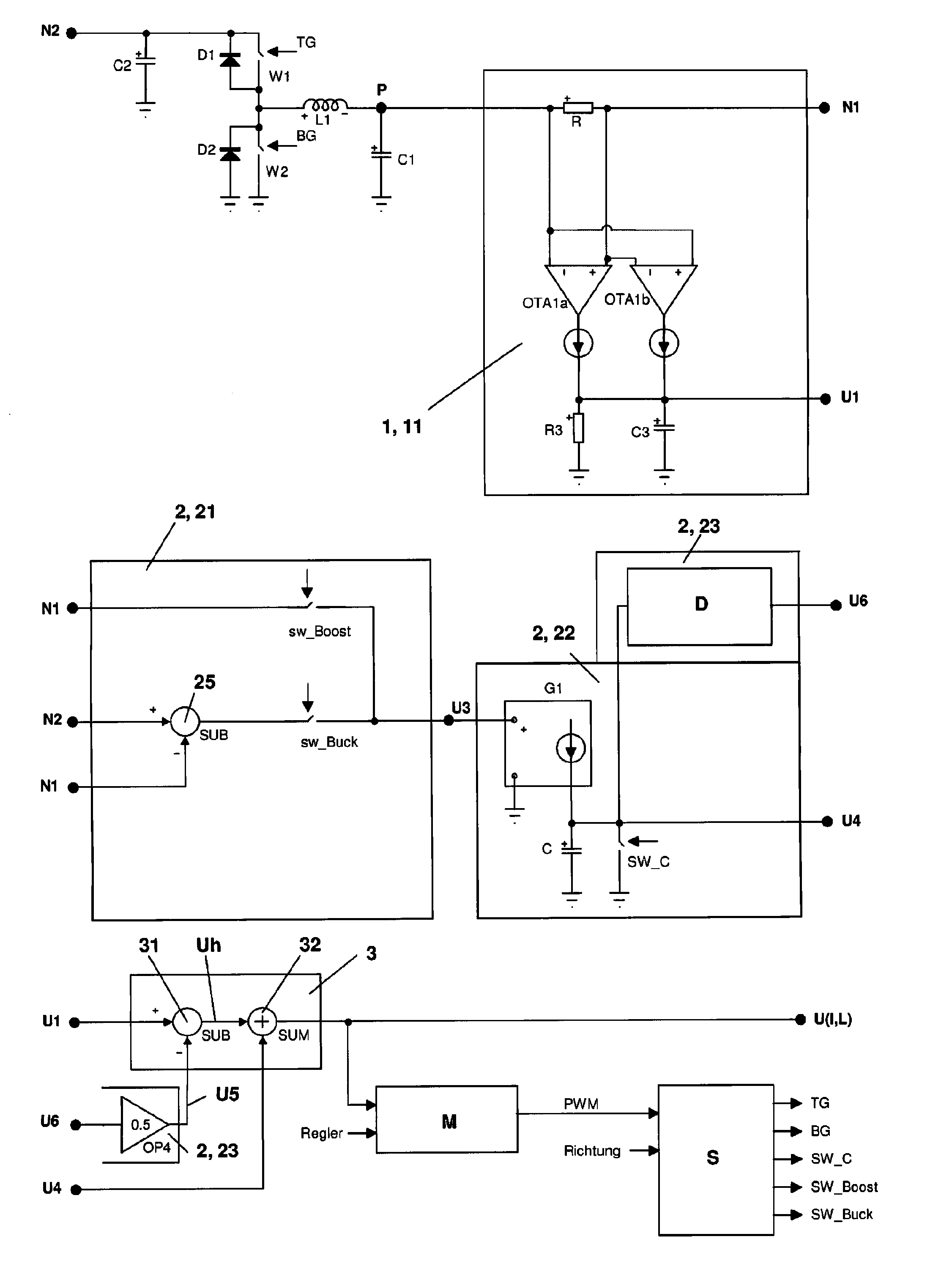
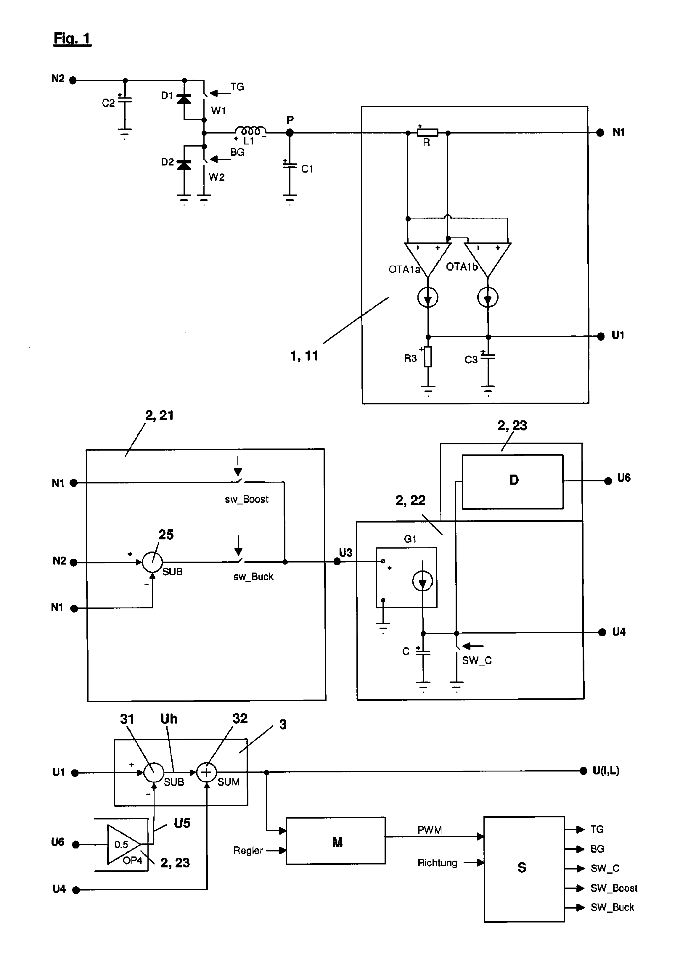
[0043]The circuit arrangement according to the invention illustrated in FIG. 1 has a bidirectional synchronous DC-to-DC converter in a power component. In this power component and / or in the DC-to-DC converter, a voltage of a first power network is converted into the voltage of a second power network—or the voltage of the second network is converted into the voltage of the first network. The flow of energy can be controlled by a corresponding co...


PUM


Abstract

A circuit for emulating a current via a power inductor of a DC-to-DC converter includesmeans for generating a first signal and operable for detecting or emulating the constant component of the current via the power inductor and having first elements for generating the first signal,means for generating a second signal or components of the second signal and operable for emulating the alternating component of the current via the power inductor, andmeans for splicing the first signal and the second signal, or the first signal and the components of the second signal, into a signal which at least partially emulates the current via the power inductor, withthe first elements of the first means including a current sensing resistor connected on the one hand to the power inductor and a first capacitor, and on the other hand to the first input and output.

Description

CROSS REFERENCE[0001]This application claims priority to PCT Application No. PCT / EP2011 / 071723, filed Dec. 5, 2011, which in turn claims priority to German Application No. 10 2010 061 042.9, filed Dec. 6, 2010, each of which are incorporated by reference in their entirety herein.TECHNICAL FIELD OF THE INVENTION[0002]The invention relates to a circuit for the purpose of at least partially emulating a current via a power inductor of a DC-to-DC converter, particularly of a bidirectional DC-to-DC converter, for example a bidirectional synchronous converter, having a first input and / or output for the purpose of connection to a first power grid, and having a second input and / or output for the purpose of connection to a second power grid.BACKGROUND OF THE INVENTION[0003]A bidirectional synchronous converter, which can also be called a “buck-boost” converter, is known from DE 696 34 709 12. A circuit is also known which can be used to sense the current via the power inductor of the switch c...

Claims


Application Information

Patent Timeline
IPC IPC(8): H02M3/156
CPCH02M3/156G01R19/0092H02M3/1582H02M1/0009
Inventor DAUB, WOLFGANG
Owner HELLA KG HUECK & CO
Learn More