Supercharge Your Innovation With Domain-Expert AI Agents!

Ac input voltage interruption detection method and circuit

a detection method and input voltage technology, applied in the field of ac input voltage interruption detection methods and circuits, can solve the problems of difficult choice of reference voltage vrefb>1/b>, inconvenient configuration of ac input voltage interruption detection circuits in the form of integrated circuits, and difficulty in ac input voltage interruption, etc., to achieve easy circuit integration and achieve the effect of easy realization

Active Publication Date: 2014-11-27
FUJI ELECTRIC CO LTD
View PDF9 Cites 7 Cited by
  • Summary
  • Abstract
  • Description
  • Claims
  • Application Information

AI Technical Summary

Benefits of technology

The present invention describes an AC input voltage interruption detection circuit that can be easily integrated into an integrated circuit, allowing for easy circuit realization. The technical effect of this invention is the ability to detect interruptions in AC input voltage in a simple and efficient manner.

Problems solved by technology

In such a case, a problem arises where erroneous determination is made that the AC input voltage is interrupted.
If the circuit is used with fixed AC voltage, this problem can be avoided by selecting a reference voltage Vref1 corresponding to a voltage that is slightly lower than the peak value of the AC input voltage, but a problem arises then in that the choice of the reference voltage Vref1 becomes difficult when the AC input voltage range is expanded in worldwide-compliant power-supply specifications.
The above-described conventional second AC input voltage interruption detection circuit does not suffer from the problem of such erroneous determination, as is the case in the conventional first AC input voltage interruption detection circuit, but requires a large resistance and / or capacitance for filtering and rectifying low-frequency components, from about 50 Hz to 60 Hz, and is therefore problematic in that the AC input voltage interruption detection circuit is not suitable for being configured in the form of an integrated circuit.

Method used


Image

  • Ac input voltage interruption detection method and circuit
  • Ac input voltage interruption detection method and circuit
  • Ac input voltage interruption detection method and circuit

Examples


Embodiment Construction

[0028]Embodiments of the present invention are explained next with reference to accompanying drawings.

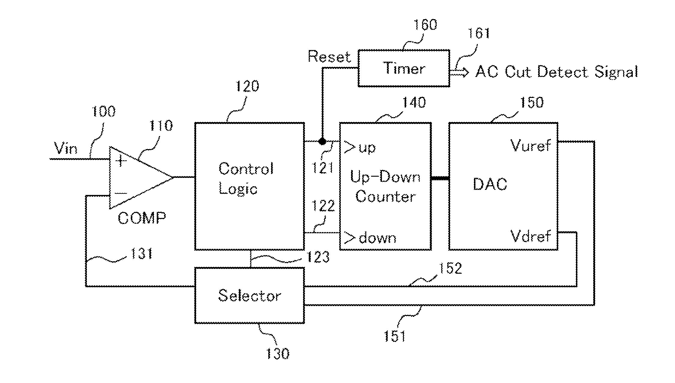
[0029]FIG. 5 is a diagram illustrating the configuration of an AC input voltage interruption detection circuit according to an embodiment of the present invention. The AC input voltage interruption detection circuit illustrated in FIG. 5 is made up of: a selector circuit 130 that selects either a class upper-limit voltage Vuref (151) or a class lower-limit voltage Vdref (152), as a reference voltage of a comparator 110, and that outputs the selection as a selector circuit output (131); a control logic 120 that controls the selector circuit 130, and that generates a count-up signal 121 or count-down signal 122 in accordance with the output of the comparator 110; an up / down counter 140 that counts up upon reception of the count-up signal 121 from the control logic 120, and that counts down upon reception of the count-down signal 122; a digital-analog converter 150 that outputs the cla...


PUM


Abstract

A selector circuit selects either a class upper-limit voltage or a class lower-limit voltage as a reference voltage of a comparator. A control logic controls the selector circuit, and generates a count-up signal or a count-down signal in accordance with the output of the comparator. An up / down counter counts up upon reception of the count-up signal from the control logic, and counts down upon reception of the count-down signal. A digital-analog converter outputs the class upper-limit voltage and the class lower-limit voltage in accordance with a digital value that is outputted by the up / down counter. A timer circuit is configured to be reset by the count-up signal from the control logic to the up / down counter.

Description

TECHNICAL FIELD[0001]The present invention relates to an AC input voltage interruption detection method and a circuit that involve detecting interruption of AC input voltage, and, for instance, shutting off a power supply or discharging capacitor that has been brought to high voltage.BACKGROUND ART[0002]AC input voltage interruption detection circuits are used for detecting interruption of AC input voltage, and for performing, for instance, shut off of a power supply that is connected with AC input voltage or discharge of capacitor that has been brought to high voltage, and are essential circuits for the safe operation of AC-DC converters and the like.[0003]FIG. 1 and FIG. 2 are diagrams for explaining a conventional first AC input voltage interruption detection circuit, and the operation thereof, as disclosed in Japanese Patent Application Publication No. 2009-165305 (FIG. 1 to FIG. 3). In FIG. 1, the voltage of a filter capacitor C0 follows AC voltage when AC input voltage is conn...

Claims


Application Information

Patent Timeline
Patent Type & Authority Applications(United States)
IPC IPC(8): G01R19/12
CPCG01R19/12G01R19/155H02M1/32G01R19/165G01R19/16528
Inventor YAMADA, KOUHEI
Owner FUJI ELECTRIC CO LTD
Features
  • R&D
  • Intellectual Property
  • Life Sciences
  • Materials
  • Tech Scout
  • Unparalleled Data Quality
  • Higher Quality Content
  • 60% Fewer Hallucinations
Learn More