Magnetic Resonance System with Whole-Body Transmitting Array

Inactive Publication Date: 2014-11-27
SIEMENS AG
View PDF3 Cites 9 Cited by
  • Summary
  • Abstract
  • Description
  • Claims
  • Application Information

AI Technical Summary

Benefits of technology

The patent text describes a system for adjusting the positions of second transmitting antennae to improve the efficiency of examining objects. The second transmitting antennae can be positioned independently from each other, allowing for better coverage and a larger fill factor. The technical effect is improved precision and accuracy in identifying and analyzing objects.

Problems solved by technology

The use of such a conventional antenna is unproblematic when the field strength of the basic magnetic field of is, for example, 1.5 Tesla.
However, at higher field strengths of the basic magnetic field (e.g., a magnetic field strength of 7 Tesla), the transmitting resonators may have low efficiency due to the short wavelength of the excitation field (e.g., proton imaging).
Thus, at greater basic magnetic field strengths, it is difficult to generate a homogeneous field distribution of the high-frequency excitation field.
Furthermore, the construction of the basic magnet is complex and cost-intensive.
The complexity and cost increase together with the strength of the basic magnetic field to be generated.
There maybe insufficient space available for a potential whole-body transmitting antenna.
However, transmitting antennae of this type may cover only a portion of the examination volume.
Due to the undefined positioning of the transmitting antennae, determining the interaction of the individual transmitting antennae in advance is difficult to near impossible.
The problems become more manifest if the transmitting antennae are flexible.
Thus, in conventional approaches, the coordinated, simultaneous operation of a plurality of such transmitting antennae is difficult or impossible.

Method used


Image

  • Magnetic Resonance System with Whole-Body Transmitting Array
  • Magnetic Resonance System with Whole-Body Transmitting Array
  • Magnetic Resonance System with Whole-Body Transmitting Array

Examples


Embodiment Construction

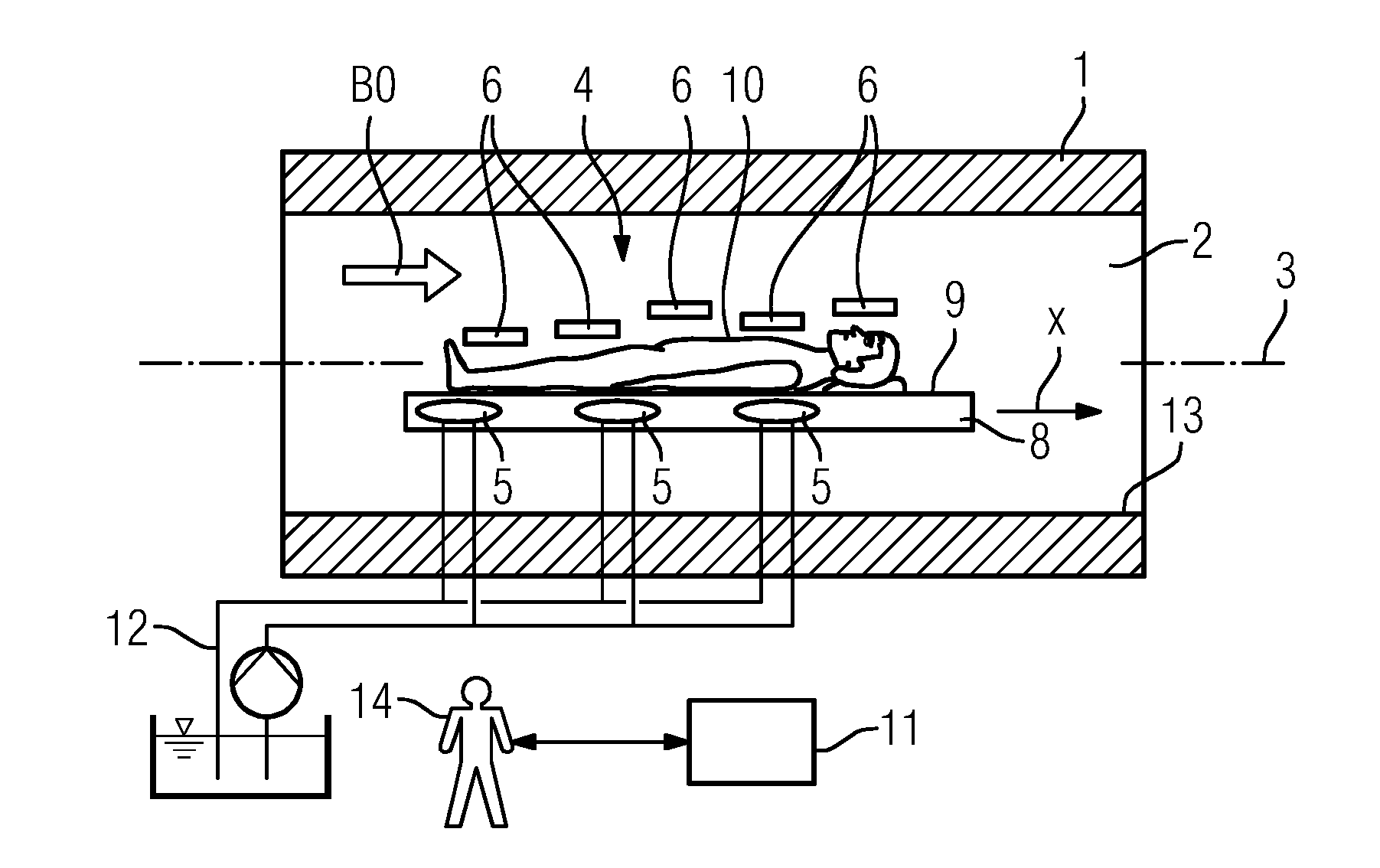
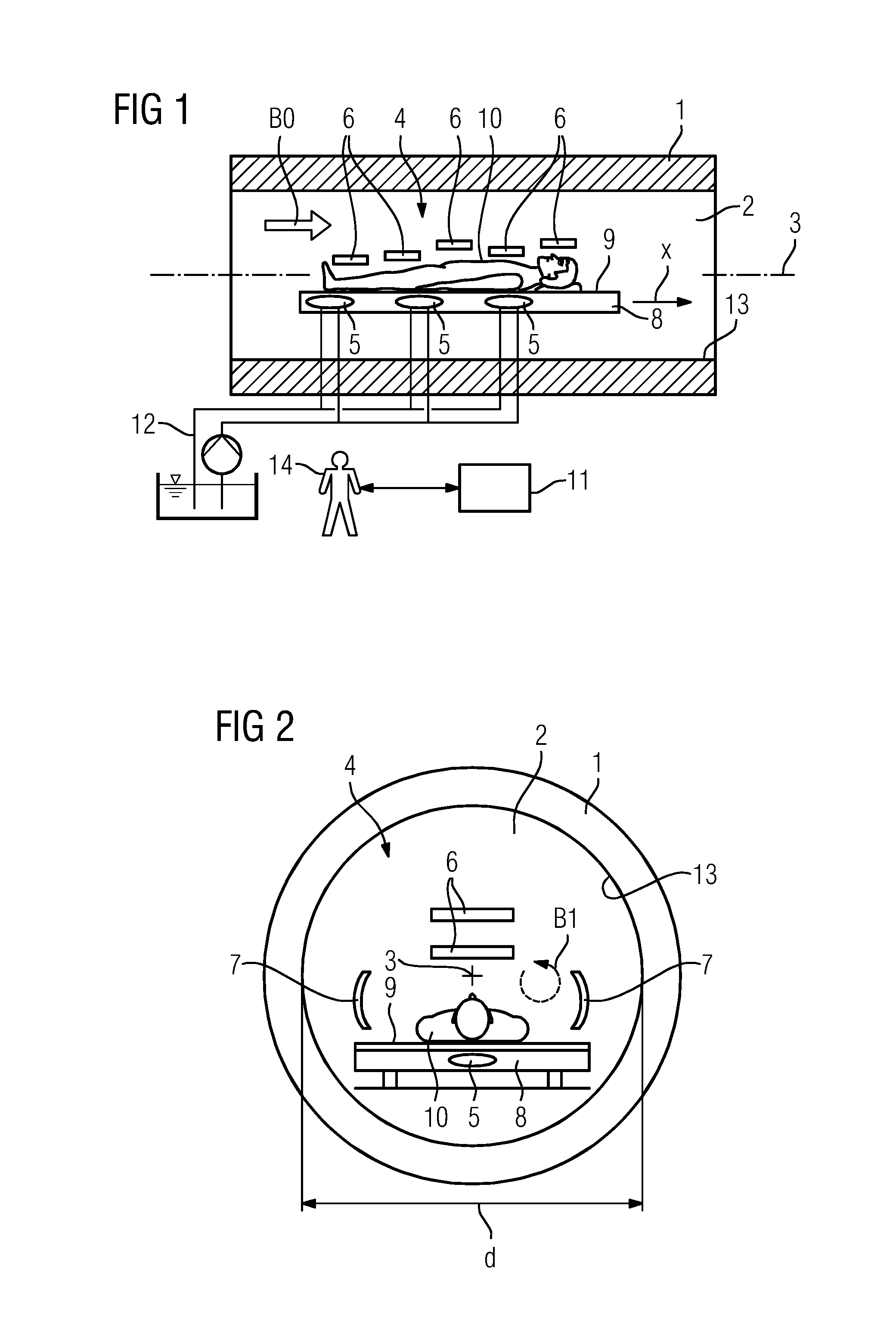
[0023]As shown in FIGS. 1 and 2, a magnetic resonance system has a basic magnet 1. The basic magnet 1 radially surrounds a cylindrical examination volume 2 of the magnetic resonance system. The examination volume 2 defines a longitudinal axis 3. The basic magnet 1 generates a basic magnetic field B0 in the examination volume 2. The basic magnetic field B0 is constant over time and is spatially homogeneous or at least substantially homogeneous inside the examination volume 2. By way of example, the basic magnetic field B0 has a strength of at least 3.0 Tesla and, in some embodiments, 7.0 Tesla. The magnetic resonance system also has a gradient system (not shown).

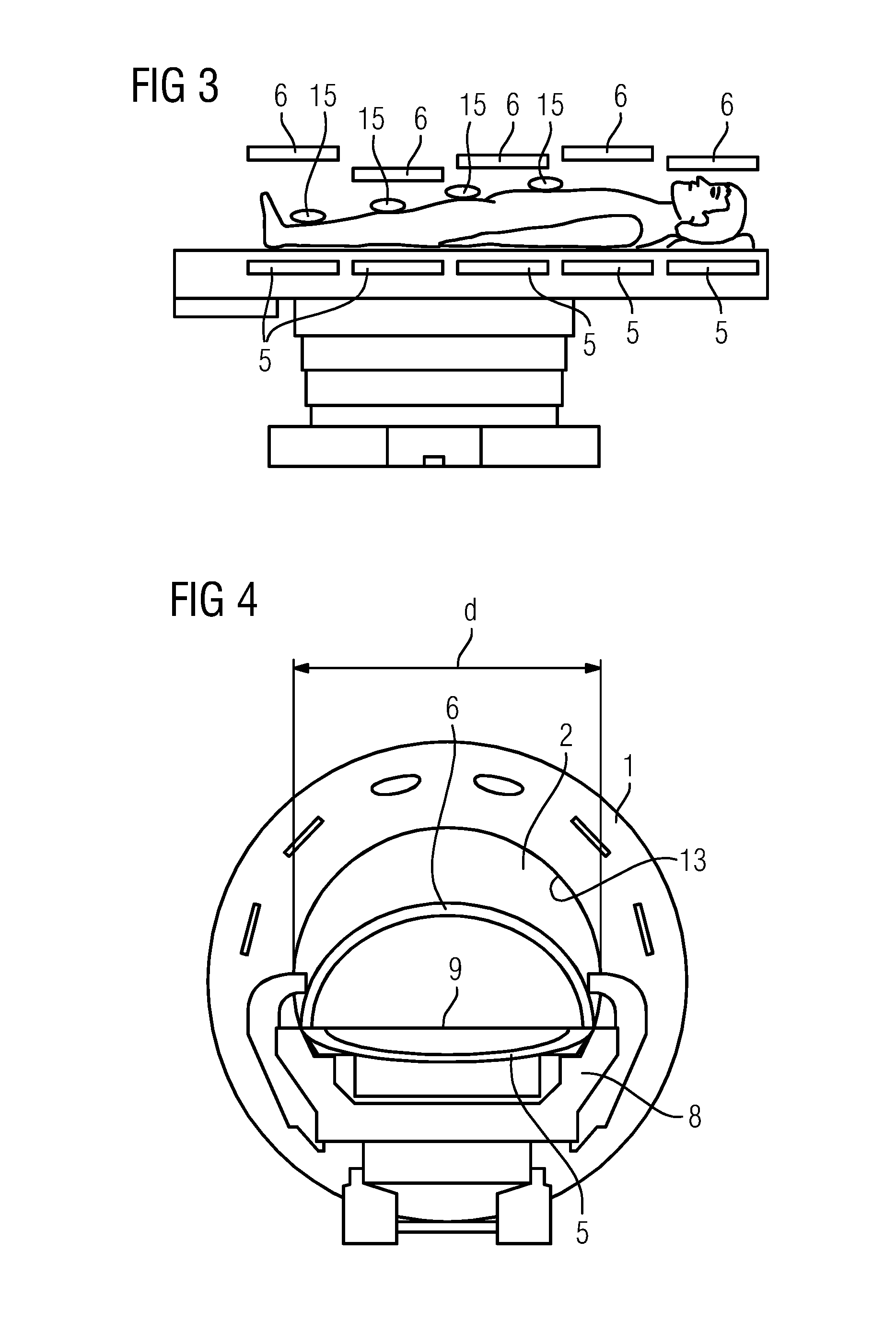
[0024]The magnetic resonance system also has a send structure 4. The send structure 4 includes at least first transmitting antennae 5 and second transmitting antennae 6. In some embodiments, the send structure 4 also includes third transmitting antennae 7. There may be a plurality of first transmitting antennae 5 and a plural...


PUM


Abstract

A magnetic resonance system includes a basic magnet that surrounds a cylindrical examination volume of the magnetic resonance system, the cylindrical examination volume defining a longitudinal axis, and a send structure configured to generate a high frequency excitation field (B1) in the examination volume. The high frequency excitation field is configured to excite an object to be examined in the examination volume, such that the object emits magnetic resonance signals. The basic magnet is configured to generate a basic magnetic field (B0) in the examination volume that is constant over time and at least substantially homogeneous spatially. The send structure includes at least first transmitting antennae and second transmitting antennae that are configured to load the examination volume with the high frequency excitation field (B1).

Description

RELATED APPLICATIONS[0001]This application claims the benefit of German Patent Application No. DE 102013209609.7, filed May 23, 2013, the entire contents of which are hereby incorporated herein by reference.TECHNICAL FIELD[0002]The present teachings relate generally to magnetic resonance systems.BACKGROUND[0003]A magnetic resonance system has a basic magnet that radially surrounds a cylindrical examination volume of a magnetic resonance system. The cylindrical examination volume defines a longitudinal axis. The basic magnet generates a basic magnetic field in the examination volume. The basic magnetic field is constant over time and at least substantially homogeneous spatially. The magnetic resonance system has a send structure (e.g., a transmission structure) that may generate a high frequency excitation field in the examination volume. The high frequency excitation field may excite an object to be examined in the examination volume, such that the object emits magnetic resonance si...

Claims


Application Information

Patent Timeline
IPC IPC(8): G01R33/38
CPCG01R33/38G01R33/3403G01R33/34084G01R33/341G01R33/3415A61B5/055G01R33/54
Inventor KIMMLINGEN, RALPHRIETSCH, NORBERT
Owner SIEMENS AG
Why Eureka
Try Eureka