Multi-view fundus camera

a fundus camera and multi-view technology, applied in the field of optics and ophthalmology, can solve the problems of stereoscopic image from a monitor, inability to select different planes, and lack of reconstruction optical segmentation, and achieve the effect of high segmentation capacity and high resolution

Inactive Publication Date: 2014-11-27
ASOCIACION IND DE OPTICA COLOR E IMAGEN AIDO +1
View PDF0 Cites 16 Cited by
  • Summary
  • Abstract
  • Description
  • Claims
  • Application Information

AI Technical Summary

Benefits of technology

[0011]To generate 3D images of the fundus, a microlens array must be inserted between the retina and the sensor of the camera that is used to photograph it, thereby forming an integral imaging system. This imaging technique allows obtaining three-dimensional photographs of the posterior pole with polychromatic light, high resolution and complete parallax. These images can be projected from an integral imaging monitor or be used to calculate a topographical map of the fundus with high segmenting capacity. The invention advantageously combines the features of a conventional fundus camera and of the integral imaging technique for generating 3D images used to solve the main drawback of stereoscopic fundus cameras and ophthalmoscopes: visual fatigue due to the vergence-accommodation conflict.

Problems solved by technology

However, as there are only two views, topographical reconstructions lack optical segmenting, i.e., it is not possible to select different planes in depth of scene in image reconstruction.
In addition, and given that stereoscopic observation is very sensitive to effects inherent to the vergence-accommodation conflict, the projection of this stereoscopic image from a monitor gives rise to enormous visual fatigue when observed for prolonged periods.
Not widely used due to its high cost, this apparatus is based on projecting a laser point focused by the eye optic on the retina and subsequently detecting the rays reflected by the retina after going through a small opening, or pinhole, limiting the entrance of the most diffused rays reflected by the retina in the detector.
Its drawback is the need to use laser illumination and the need to perform a point-to-point scan of the entire area of the retina to be observed until obtaining the final three-dimensional image.
While laser illumination gives images a monochromatic appearance, differing greatly from the chromaticity of images obtained with the retinal fundus camera, the need to scan demarcates the number of pixels of the final image and requires a certain amount of time until the entire region of interest is scanned.
While axial resolution is better than that of the ophthalmoscope, transverse resolution is worse.
Its drawbacks are its high cost, image monochromaticity and the limited number of pixels.

Method used


Image

  • Multi-view fundus camera
  • Multi-view fundus camera
  • Multi-view fundus camera

Examples


Embodiment Construction

[0017]An embodiment of the invention which must not be considered with a limiting character is described below in reference to the drawings.

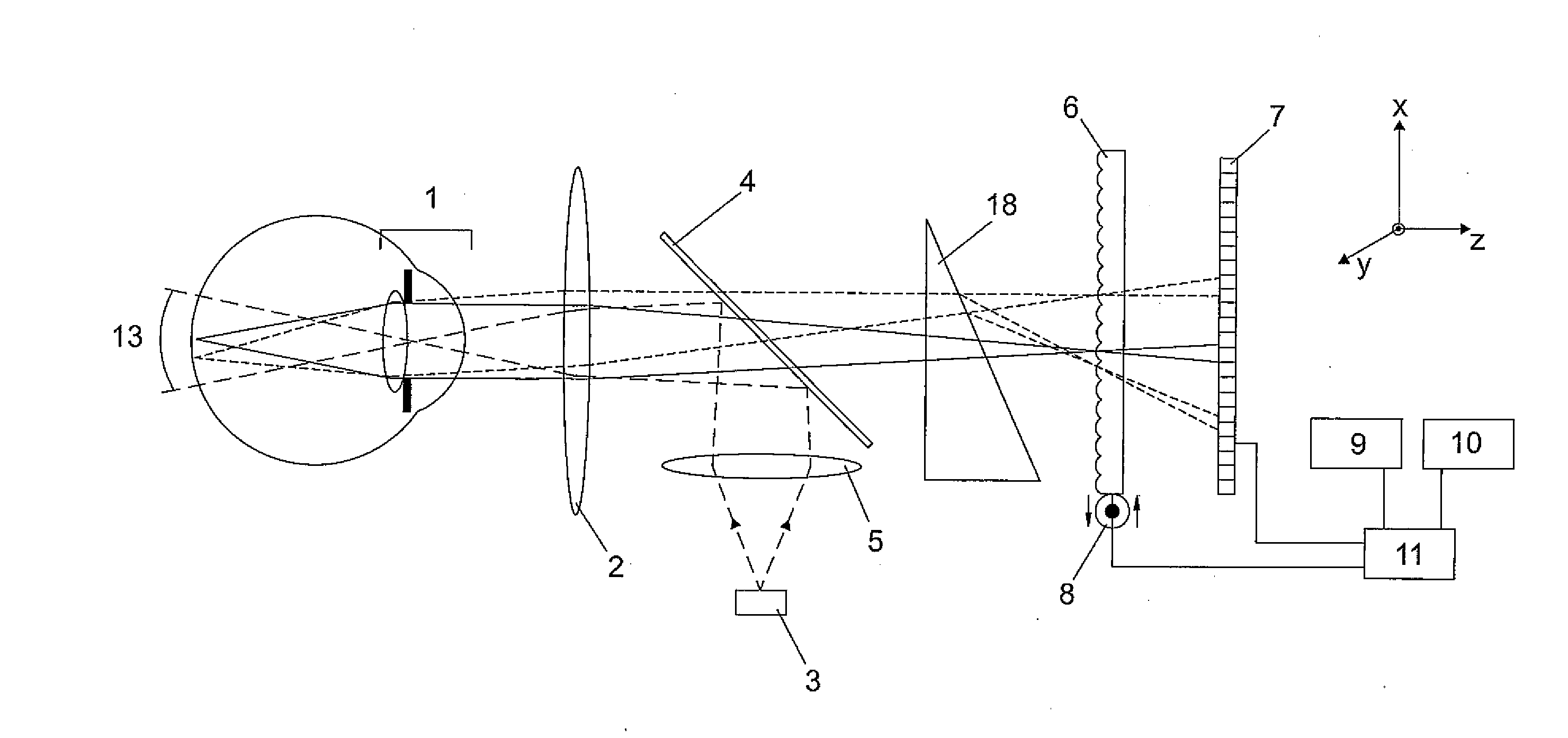
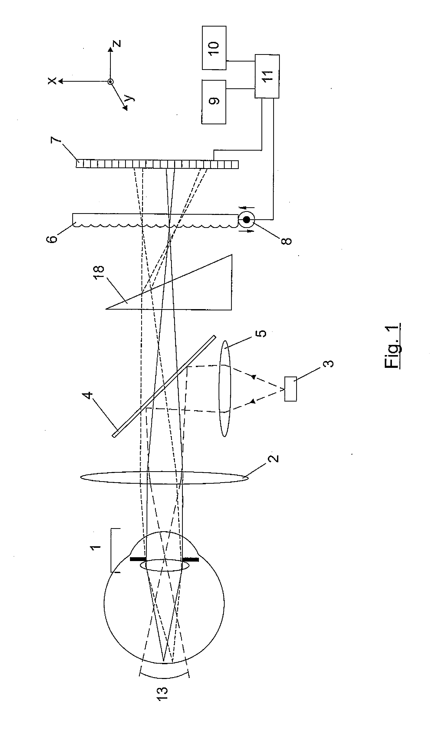
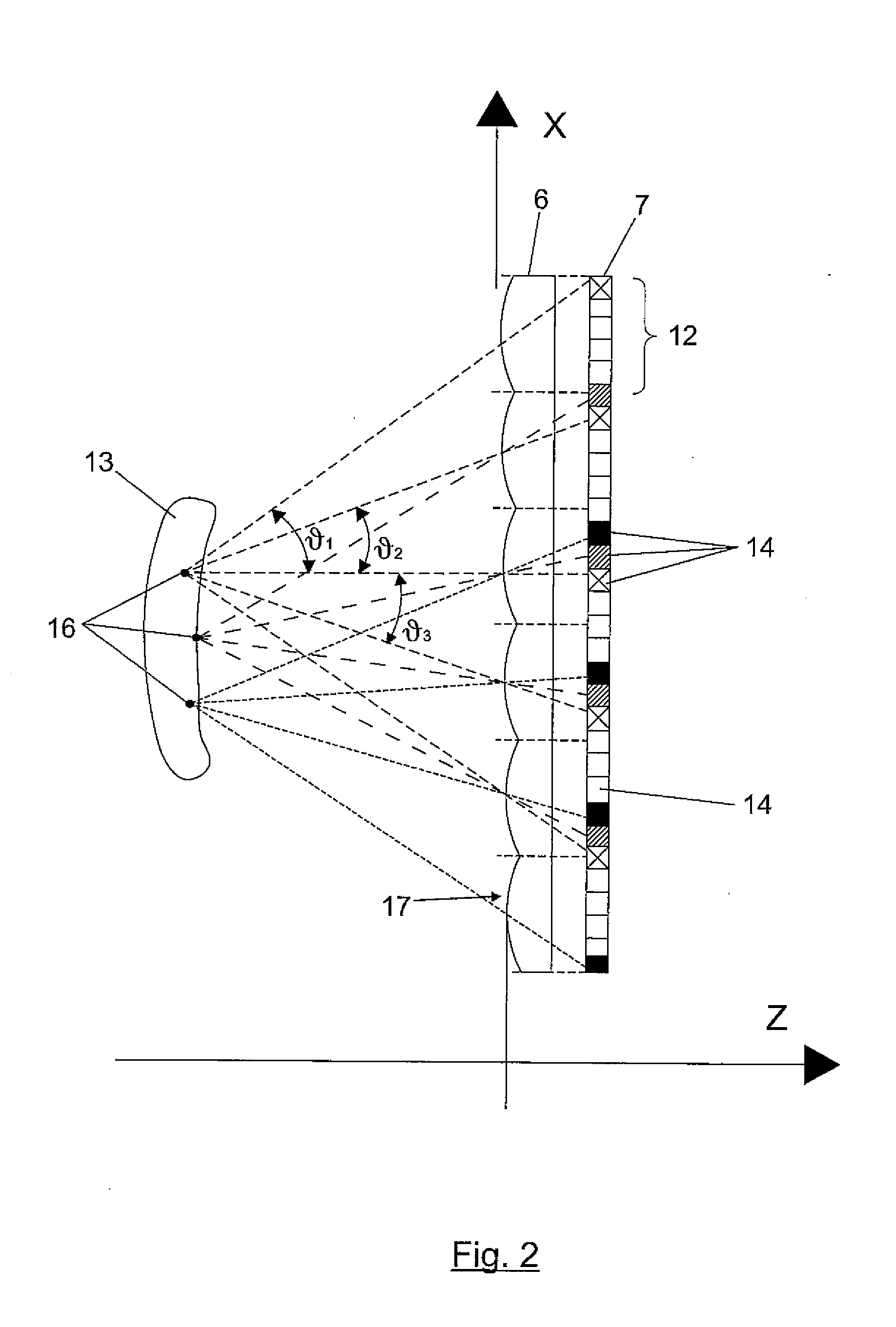
[0018]Applying the concept of integral imaging to the retinal photograph allows recording a large number of views of the fundus (13) in a single photograph (integral photograph).

[0019]As seen in FIG. 1, a light source (3) is projected on the fundus (13) through an optical system (5), (4) and (2) which also considers that of the eye (1). The light reflected by the fundus passes through the microlenses forming the array (6), striking the sensor (7).

[0020]An electromechanical displacement device (8), for example a piezoelelectric device, which transversely displaces the microlens array (6), thus increasing the number of effective microlenses, can be used to increase resolution of the integral imaging system.

[0021]An electronically tunable linear phase modulator (18), also known as phase wedge or electro-optical deflector, (e.g., a liquid crystal di...


PUM


Abstract

The invention relates to a fundus camera that incorporates an integral imaging system for capturing an integral photograph of the fundus. This integral photograph enables projecting a three-dimensional image and generating topographical maps of the fundus. The fundus camera can function plenoptically and thus zoom onto a two-dimensional image generated from the integral photograph. The proposed equipment consists of an optical system for illuminating the fundus and an optical system forming the integral image capture system. This capture system includes an ophthalmoscopic lens, a microlens array and a sensor, and it allows recording, in a single shot, multiple views of the fundus. To improve the resolution of the integral photograph, the capture system has a device that allows displacing the microlens array by a few microns.

Description

FIELD OF THE ART[0001]The present invention is comprised in the field of optics and ophthalmology. It specifically relates to a fundus camera that captures an integral photograph of the fundus. Based on this integral photograph, it is possible to project three-dimensional images of the fundus, generate topographical maps of the fundus and perform optical sectioning on the image that is obtained.BACKGROUND[0002]Fundus is a term used to refer to the posterior pole of the eyeball. This part primarily comprises the retina, the macula and the optic nerve, and the fundus is usually examined to detect eye diseases, also being possible to detect diseases not directly associated with the eye, such as diabetes or hypertension.[0003]The most common devices for non-invasive examination of the retinal fundus are the ophthalmoscope and the fundus camera. These devices are very useful for a first diagnosis and for monitoring retinal pathologies. To improve the performances of said equipment, the p...

Claims


Application Information

Patent Timeline
Patent Type & Authority Applications(United States)
IPC IPC(8): A61B3/12A61B3/14
CPCA61B3/14A61B3/12
Inventor MARTINEZ CORRAL, MANUELPONS MARTI, AMPAROSAAVEDRA TORTOSA, GENARONAVARRO FRUCTUOSO, HECTORMARTINEZ CUENCA, RAULTOLOSA RUIZ, ANGELALCON, NATIVIDAD
Owner ASOCIACION IND DE OPTICA COLOR E IMAGEN AIDO
Why Eureka
Try Eureka