Talus surface implant

Active Publication Date: 2014-11-27
ARTHREX
View PDF4 Cites 54 Cited by
  • Summary
  • Abstract
  • Description
  • Claims
  • Application Information

AI Technical Summary

Benefits of technology

[0013]In a further embodiment a cushion is provided on the top surface. This is preferably for decreasing friction and for damping. The cushion may be made of a material like polycarbonate-urethane (PCU).
[0014]In another embodiment the bottom side of the implant comprises a plurality of planar segments. These simplify preparation of the bone, as multiple planes can be easier machined than a complex arc shaped surface.
[0015]A further embodiment is a trial implant which may be used as a drilling gauge and which may also be used for testing the fit of the implant. It preferably has at least one hole to allow drilling of the at leas

Problems solved by technology

With the tibia in place on the surface of the implant, it is

Method used


Image

  • Talus surface implant
  • Talus surface implant
  • Talus surface implant

Examples


Embodiment Construction

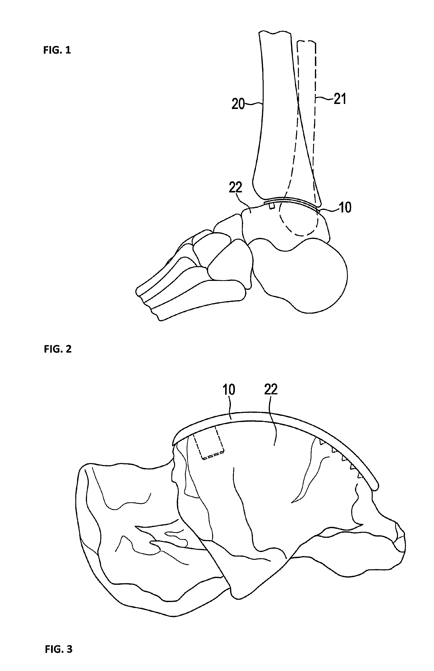
[0028]FIG. 1 shows in details the bones of a human ankle. The ankle is a synovial hinge joint connecting the distal ends of the tibia 20 and fibula 21 in the lower limb with the proximal end of the talus 22 bone in the foot. The talus surface implant 10 is located at the proximal side of the talus.

[0029]FIG. 2 shows the talus implant 10 located on the proximal side of the talus 22. One of the posts 17 for holding the implant and some of the spikes 19 are also shown.

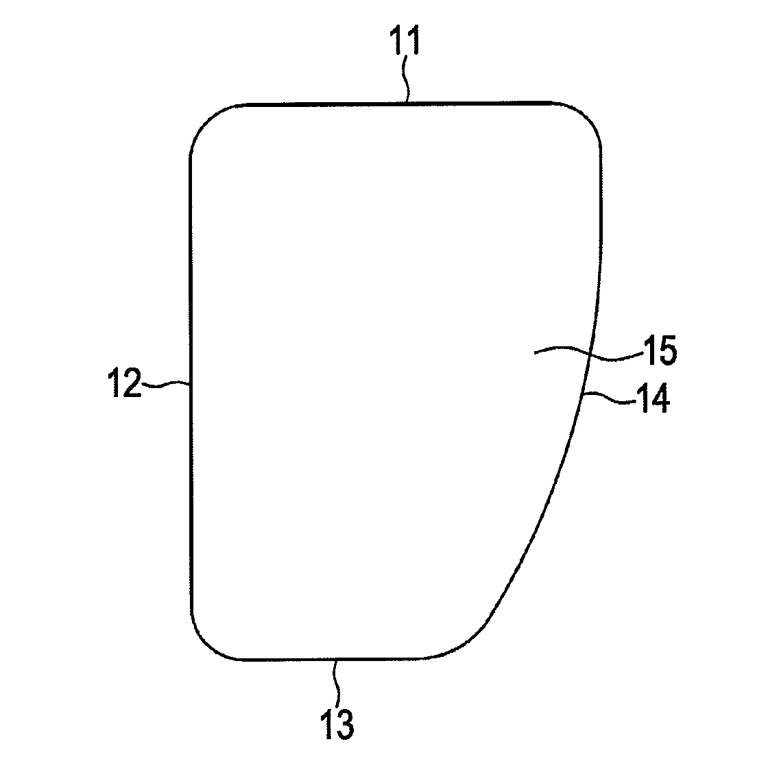
[0030]FIG. 3 shows the implant 10 in a top view. The implant has a top side 15 which interfaces with the tibia. The outer contour of the implant is defined by a front side 11 directed anterior (towards the toes) and opposed thereto (posterior) a shorter rear side 13. Between these is an inner side 12 and opposed thereto an outer side 14. The outer side 14 is slightly curved to adapt to the surface of the talus from the longer front side 11 to the shorter rear side 13.

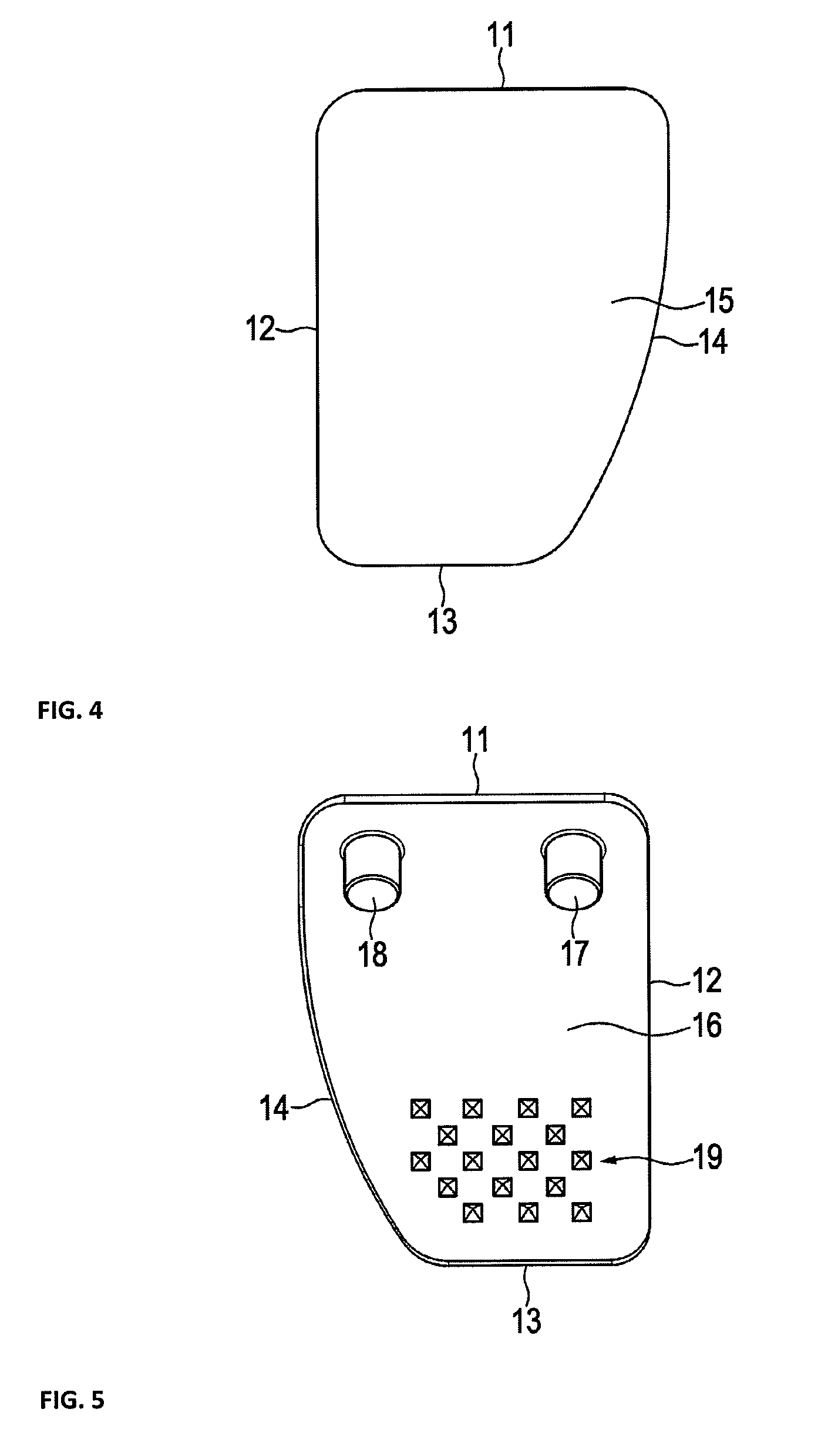
[0031]In FIG. 4 the implant is shown in a bottom view. ...


PUM


Abstract

A talus surface implant has an arc shaped body with a top side interfacing to the tibia and a bottom side having at least one post for interfacing with holes in the talus and a plurality of spikes for interfacing with the surface of the talus. Preferably the implant is double arc shaped.

Description

PRIORITY CLAIM[0001]This is a continuation of pending International Application No. PCT / IB2013 / 000658, filed on Apr. 12, 2013, which designates the United States and claims priority to European Application No. 12163997.5, filed on Apr. 12, 2012.BACKGROUND OF THE INVENTION[0002]1. Field of the Invention[0003]The present invention relates to a talus implant system and a method for surgical reconstitution of the ankle.[0004]2. Description of Relevant Art[0005]The ankle is a synovial hinge joint connecting the distal ends of the tibia and fibula in the lower limb with the proximal end of the talus bone in the foot. For treatment of arthrosis or damage of the joint treatments like ankle arthrodesis and ankle arthroplasty are known. The US patent application publication 2002 / 0055744 A1 discloses an ankle prosthesis which requires a comparatively complex insertion procedure and massive intrusion into the body of the patient.[0006]US 2010 / 0057216 A1 discloses a talus resurfacing system, whe...

Claims


Application Information

Patent Timeline
IPC IPC(8): A61F2/42A61F2/30
CPCA61F2/4202A61F2002/30841A61F2002/4207A61F2/30756A61F2002/30878A61F2002/30891
Inventor MICHEL, GERLINDEBACHMAIER, SAMUEL
Owner ARTHREX
Why Eureka
Try Eureka