This helps you quickly interpret patents by identifying the three key elements:
Problems solved by technology
Method used
Benefits of technology
[0016]According to the present invention, heat used in the vapor chamber c
Problems solved by technology
However, in the technology of Patent Document 1, the heat used to generate the vapor of the
Method used
Image
Click on the blue label to locate the original text in one second.
Reading with bidirectional positioning of images and text.
Examples
Example
EXAMPLE 1
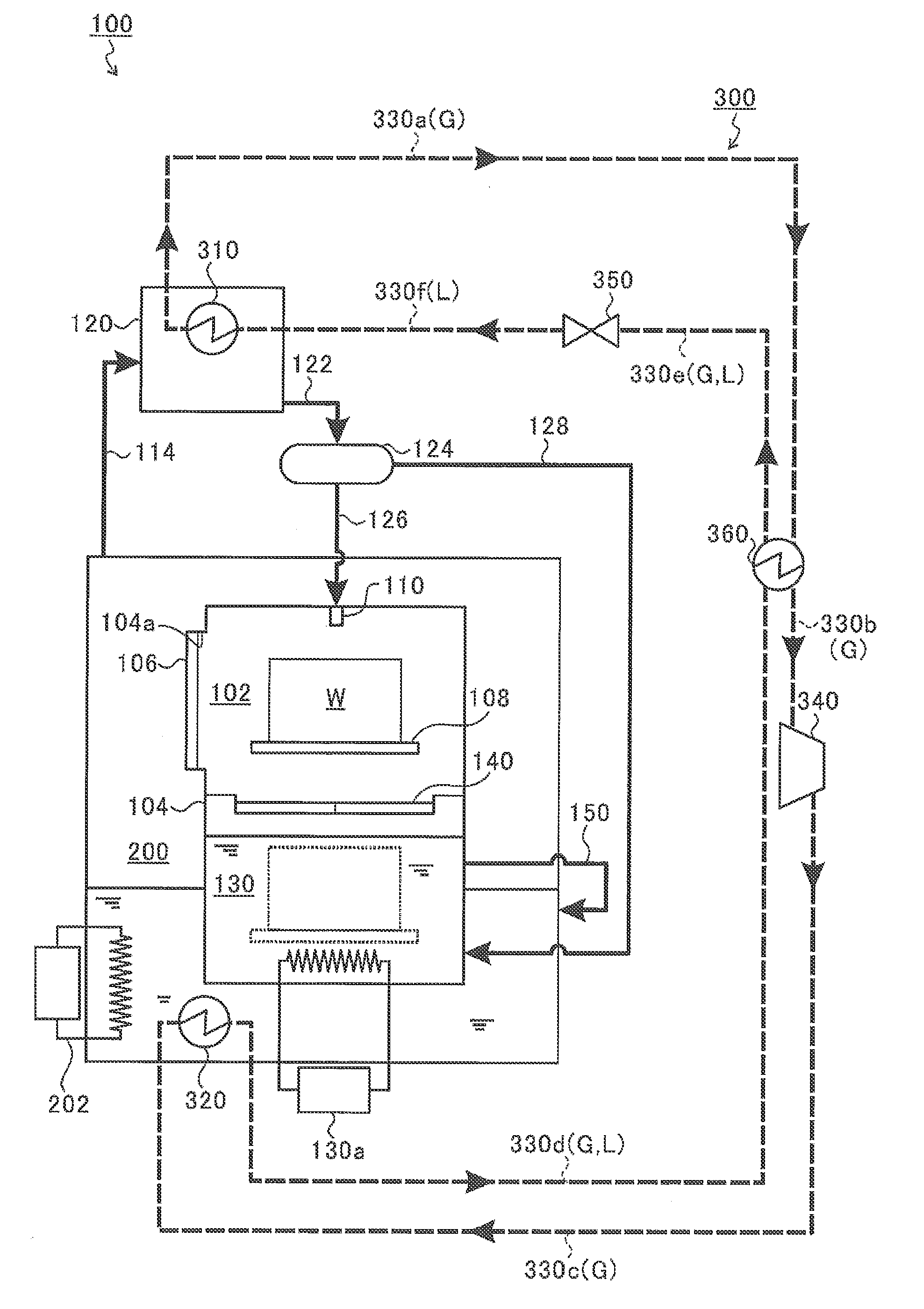
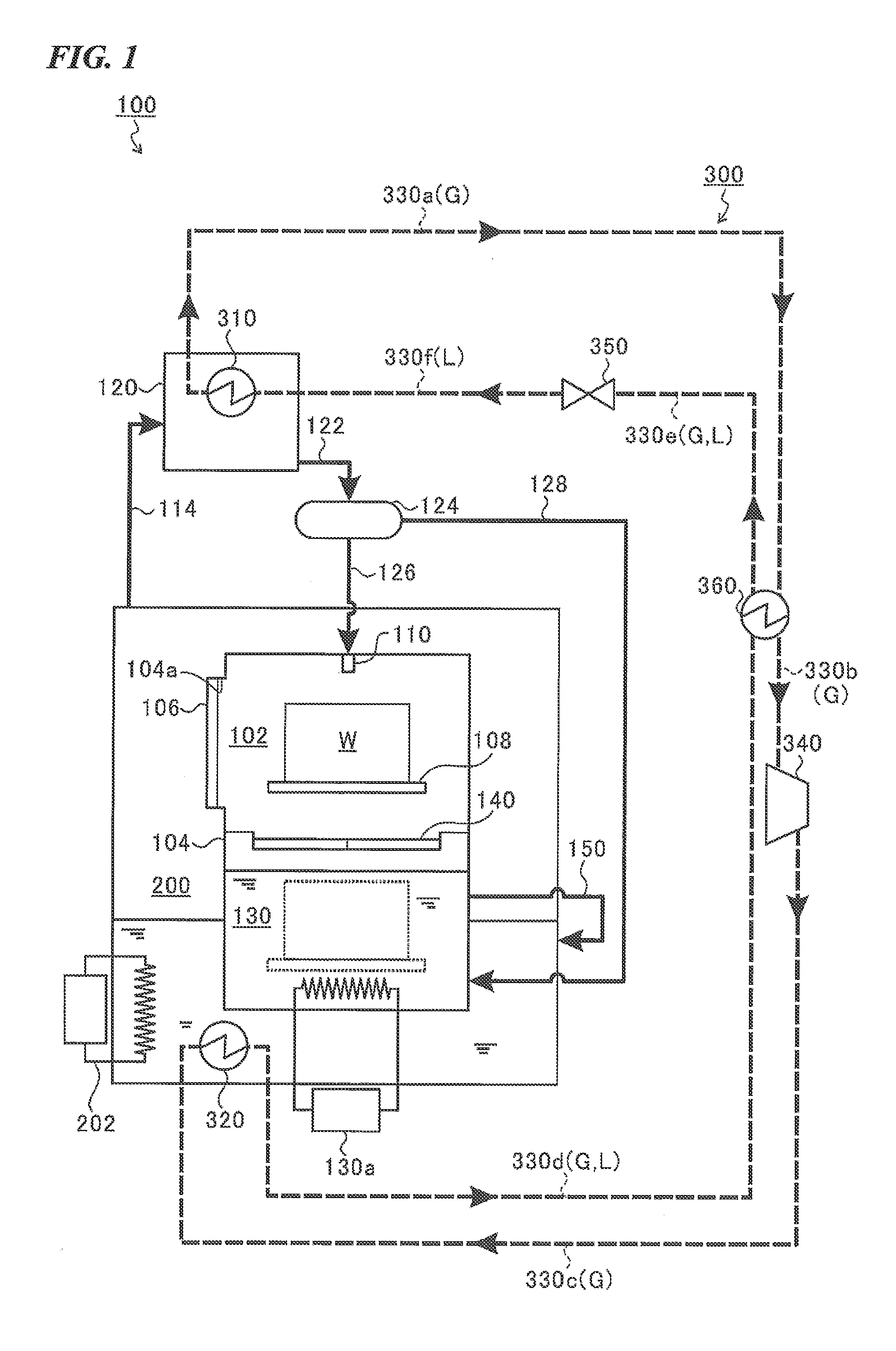
[0055]In a state in which the third heat exchanger 360 is not provided, in the case in which the vapor chamber 200 generates the vapor at 120° C. (Case 1) and the case in which the vapor chamber 200 generates the vapor at 110° C. (Case 2), a temperature of the thermal medium, energy consumption (kW) of the compressor 340, a thermal dose (kW) of the vapor chamber 200 by the second heat exchanger 320 were investigated.
[0056]In the vacuum cleaning device of the related art having no heat pump unit, when the vapor chamber generates the vapor at 120° C., the heater requires a capacity of 35 kW (normally, 36 kW upon initial operation).
[0057]As described in Table 1, it will be appreciated that, in Case 1, the thermal medium was heated to 92° C. to 95° C. in the first heat exchanger 310, heated to 95° C. to 132° C....
Example
EXAMPLE 2
[0059]In a state in which the third heat exchanger 360 is provided, in the case in which the vapor chamber 200 generates the vapor at 120° C. (Case 3) and the case in which the vapor at 110° C. is generated (Case 4), a temperature of the thermal medium, energy consumption (kW) of the compressor 340 and a thermal dose (kW) of the vapor chamber 200 by the second heat exchanger 320 were investigated.
[0060]As described in Table 2, it will be appreciated that, in Case 3, the thermal medium is heated to 92° C. to 95° C. in the first heat exchanger 310, heated to 95° C. to 103° C. by the third heat exchanger 360, heated to 103° C. to 139° C. by the compressor 340, cooled to 139° C. to 128° C. in the second heat exchanger 320 and cooled to 128° C. to 123° C. by the third heat excha...
PUM
Property
Measurement
Unit
Power
aaaaa
aaaaa
Abstract
This vacuum cleaning device is provided with: a vapor chamber in which vapor of a hydrocarbon-based cleaning agent is generated; a condensation chamber; a first heat exchanger in which heat exchange between the vapor and a heating medium is carried out; a cleaning chamber in which a workpiece can be cleaned under vacuum by the condensed cleaning agent that has been generated in the condensation chamber; a compressor that adiabatically compresses and further heats the heating medium that was heated by the first heat exchanger; a second heat exchanger that carries out heat exchange between the heating medium heated by the compressor and the hydrocarbon-based cleaning agent in the vapor chamber; and a vacuum unit that further cools the heating medium that has been cooled by the second heat exchanger by forcing vacuum expansion of the heating medium. The heating medium cycles through the first heat exchanger, the compressor, the second heat exchanger, and the vacuum unit by the heating medium cooled by the vacuum unit being returned to the first heat exchanger.
Description
[0001]This application is a continuation application based on a PCT Patent Application No. PCT / JP2013 / 061411, filed Apr. 17, 2013, whose priority is claimed on Japanese Patent Application No. 2012-100312, filed Apr. 25, 2012. The contents of both the PCT application and the Japanese Patent Application are incorporated herein by reference.TECHNICAL FIELD[0002]The present invention relates to a vacuum cleaning device configured to supply vapor of a hydrocarbon-based cleaning agent into a decompressed cleaning chamber and clean a workpiece.BACKGROUND ART[0003]In the related art, the vacuum cleaning device disclosed in Patent Document 1 for example, is known. In such a vacuum cleaning device, first, a decompression process of decompressing a vapor cleaning and drying chamber into which a workpiece is loaded using a vacuum pump is performed, and then a vapor cleaning process of supplying vapor of a hydrocarbon-based cleaning agent into the vapor cleaning and drying chamber to clean the w...
Claims
Application Information
Patent Timeline
Application Date:The date an application was filed.
Publication Date:The date a patent or application was officially published.
First Publication Date:The earliest publication date of a patent with the same application number.
Issue Date:Publication date of the patent grant document.
PCT Entry Date:The Entry date of PCT National Phase.
Estimated Expiry Date:The statutory expiry date of a patent right according to the Patent Law, and it is the longest term of protection that the patent right can achieve without the termination of the patent right due to other reasons(Term extension factor has been taken into account ).
Invalid Date:Actual expiry date is based on effective date or publication date of legal transaction data of invalid patent.